Specifications
Page 19 of 90 057-233 ISSUE: 1
2.9.2 DSENET® FOR EXPANSION MODULES
NOTE: As a termination resistor is internally fitted to the host controller, the host
controller must be the ‘first’ unit on the DSENet®. A termination resistor MUST be fitted to the
‘last’ unit on the DSENet®. For connection details, you are referred to the section entitled
‘typical wiring diagram’ elsewhere in this document.
DSENet® is the interconnection cable between the host controller and the expansion module(s) and
must not be connect to any device other than DSE equipment designed for connection to the
DSENet®
Cable type Two core screened twisted pair
Cable characteristic
impedance
120Ω
Recommended cable Belden 9841
Belden 9271
Maximum cable length 1200m (¾ mile) when using Belden 9841 or direct equivalent.
600m (666 yds) when using Belden 9271 or direct equivalent.
DSENet® topology “Daisy Chain” Bus with no stubs (spurs)
DSENet® termination
120Ω. Fitted internally to host controller. Must be fitted externally to the
‘last’ expansion module by the customer.
Maximum expansion
modules
Total 6 devices made up of DSE2130 (up to 2), DSE2157 (up to 2),
DSE2548 (up to 2)
This gives the possibility of :
Maximum 16 additional inputs (DSE2130)
Maximum 20 additional relay outputs (DSE2157)
Maximum 20 additional LED indicators (DSE2548)
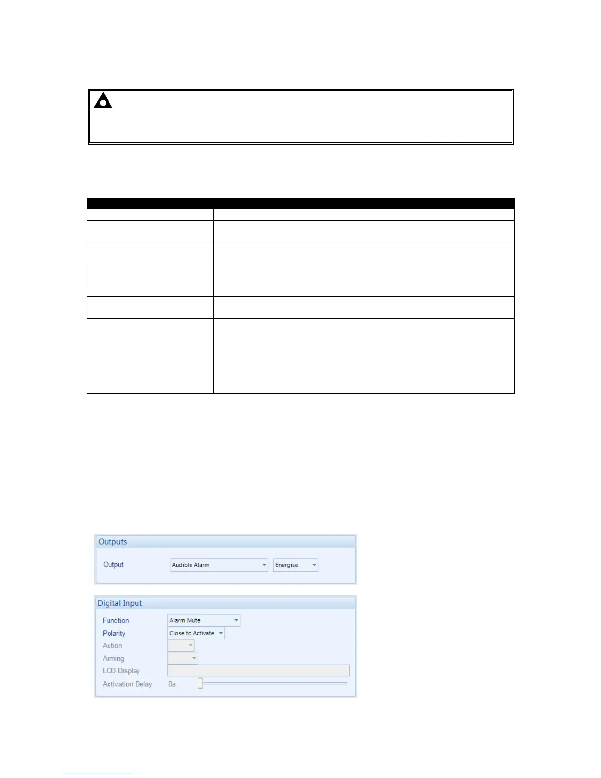
2.10 ADDING AN EXTERNAL SOUNDER TO THE APPLICATION
When an external alarm or indicator is required, this can be achieved by using the DSE Configuration
Suite PC software to configure an auxiliary output for “Audible Alarm”, and by configuring an auxiliary
input for “Alarm Mute” (if required).
The audible alarm output activates and de-activates at the same time as the module’s internal
sounder. The Alarm mute input and internal alarm mute button activate ‘in parallel’ with each other.
Either signal mutes both the internal sounder and audible alarm output.
Example of configuration to achieve external sounder with external alarm mute button: