Do you have a question about the DSE 335 and is the answer not in the manual?
Describes related DSE publications and third-party documents.
Lists installation instruction documents from DSE.
Lists DSE training guides for specific subjects.
Defines short names for modules/controllers in the DSEATS range.
Details UL certification requirements for terminals, conductors, and circuits.
Describes terminal connector types, cable size, and fittings.
Details module power supply voltage, current, and protection.
Specifies voltage sensing range, resolution, and accuracy for instrumentation.
Details measurement type, sample rate, and accuracy for current sensing.
Details correct CT primary polarity for accurate kW readings.
Describes digital input specifications including thresholds and voltage.
Describes the types and ratings of configurable outputs.
Lists available communication ports like USB, RS232, and RS485.
Details USB connection for PC configuration and controller monitoring.
Describes RS485 port capabilities for point-to-point connections.
Provides overall dimensions and panel cutout information.
Details DSENet topology, cable, and maximum expansion modules.
Explains configuring auxiliary outputs for external sounders.
Provides overall dimensions and panel cutout information.
Specifies module dimensions in mm and inches.
Specifies the required panel cutout dimensions in mm and inches.
Details how to use the supplied fixing clips for panel mounting.
Describes integral cable tie fixing points on the module rear for wiring.
Lists applicable industry standards the module conforms to.
Details enclosure protection ratings including IP and NEMA.
Explains the meaning of IP classification codes for enclosure protection.
Explains NEMA classification ratings and their relation to IP ratings.
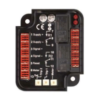
Describes the rear panel terminal functions and layout for connections.
Details configurable digital inputs J-L and DSENet terminals.
Details configurable volt-free outputs E & F.
Details connections for load switching and S2 voltage sensing.
Details connections for S1 voltage sensing.
Details connections for load current transformers.
Explains terminal connections based on wiring topology.
Explains CT primary and secondary connection details.
Details configurable volt-free changeover outputs C & D.
Details the USB connector for PC configuration.
Details the RS485 connector pinout and cable type.
Details the RS232 connector pinout.
Provides typical wiring diagrams for system installation.
Shows a typical wiring diagram for 3-phase, 4-wire with earth fault protection.
Introduces alternative AC wiring topologies for generators.
Shows wiring for 3-phase, 4-wire without earth fault protection.
Shows wiring for single phase with restricted earth fault.
Shows wiring for single phase without earth fault.
Shows wiring for 2-phase (L1&L2) with restricted earth fault.
Shows wiring for 2-phase (L1&L2) without earth fault.
Shows wiring for 2-phase (L1&L3) with restricted earth fault.
Shows wiring for 2-phase (L1&L3) without earth fault measuring.
Shows wiring for 3-phase, 4-wire with unrestricted earth fault.
Discusses different earth system configurations: negative, positive, and floating.
Explains wiring connections for a negative earth system.
Explains wiring connections for a positive earth system.
Explains wiring connections for a floating earth system.
Explains the main status display, navigation, LEDs, and buttons.
Explains the status LEDs for S1 and S2 availability and load status.
Details the function of each control push-button.
Explains the Stop/Reset button functionality.
Explains the Manual mode button functionality.
Explains the Auto mode button functionality.
Explains the alarm mute and lamp test function.
Explains how to view latest transfer details.
Explains manual S1 load transfer control.
Explains manual S2 load transfer control.
Details how to navigate and view instrument pages.
Shows configurable LCD page and scroll timers.
Describes the module's home/status page.
Lists electrical values displayed for S1.
Lists electrical values displayed for S2.
Lists information displayed about the module configuration.
Describes measured values from expansion modules.
Explains where to find active alarms.
Details the module's event logging capabilities.
Describes serial port functions.
Details RS232 serial port and modem connection.
Explains the modem initialisation process.
Describes diagnostic screens for modem issues.
Details RS485 serial port and Modbus configuration.
Provides examples of Modbus communication requests.
Explains the built-in scheduler function.
Provides information about module variant and firmware.
Explains how to view the latest transfer details.
Describes user-configurable LEDs.
Provides a quick start guide to module operation.
Details the procedure for starting S2 (generator).
Details the procedure for stopping S2 (generator).
Describes the starting sequence in manual mode.
Explains when S2 is available in manual mode.
Describes the stopping sequence in manual mode.
Describes waiting states in automatic mode.
Describes the starting sequence in automatic mode.
Explains when S2 is available in automatic mode.
Describes the stopping sequence in automatic mode.
Details the Test On Load mode.
Details the Test Off Load mode.
Details the Prohibit Return mode.
Explains scheduler behavior in Stop mode.
Explains scheduler behavior in Manual mode.
Explains scheduler behavior in Auto mode.
Explains the load shedding control scheme.
Describes how alarms are displayed on the LCD.
Describes non-critical status indications.
Details warning conditions and their display.
Details electrical trip conditions and handling.
Explains navigation buttons for menu and value changes.
Details how to access the configuration editor.
Details how to edit parameters within the editor.
Lists adjustable parameters for Bank 1 scheduler.
Lists adjustable parameters for Bank 2 scheduler.
Lists symptoms and remedies for starting problems.
Lists symptoms and remedies for loading issues.
Lists symptoms and remedies for alarm conditions.
Lists symptoms and remedies for communication issues.
Lists symptoms and remedies for measurement inaccuracies.
Provides remedies for miscellaneous configuration issues.
Lists part numbers for connector plugs, fixing clips, and sealing gaskets.
Details DSENet expansion modules and their part numbers.
Details WEEE disposal requirements.