Description of Controls
Page 53 of 90 057-233 ISSUE: 1
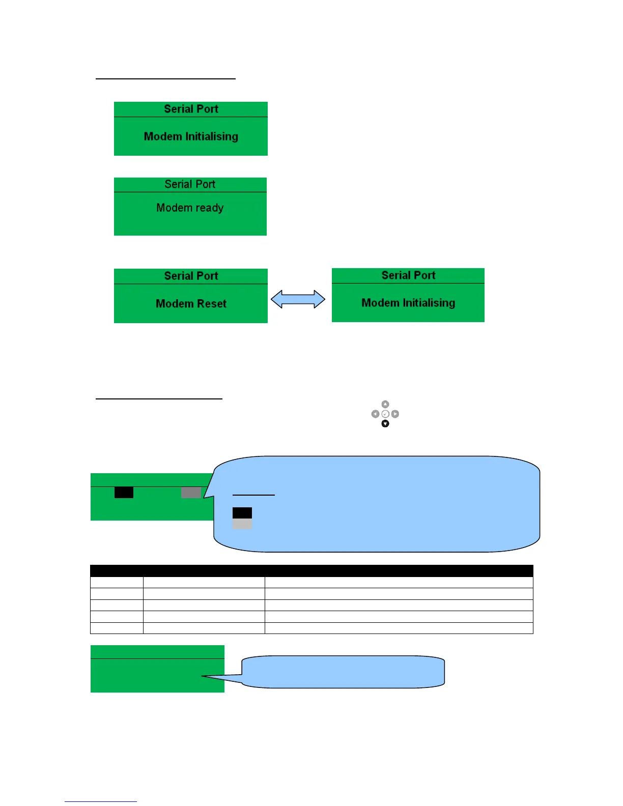
Modem Initialisation Sequence
1) The modem attempts to communicate to the module
2) If the Modem and module communicate successfully:
3) In case of communication failure between the modem and module, the modem is automatically
reset and initialisation is attempted once more:
In the case of a module that is unable to communicate with the modem, the display continuously
cycles between ‘Modem Reset’ and ‘Modem Initialising’ as the module resets the modem and
attempts to communicate with it again, this continues until correct communication is established
with the modem. In this instance, check connections and verify the modem operation.
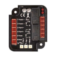
Module Modem Diagnostics
Modem diagnostic screens are included; press the Scroll Down button when viewing the
RS232 Serial Port instruments to cycle to the available screens. If modem communication problems
are experiencied, this information aids troubleshooting.
Serial Port
RTS Request to Send Flow Control
CTS Clear to Send Flow Control
DSR Data Set Ready Ready to Communicate
DTR Data Terminal Ready Ready to Communicate
DCD Data Carrier Detect Modem is Connected
Modem Commands
Tx: AT+IPR=9600
Rx: OK
Shows the state of the modem communication lines. These can
help diagnose connection problems.
Example:
RTS A dark background shows the line is active.
RTS A grey background shows that the line is toggling high and low
RTS No background indicates that the line is inactive