Installation
057-233 ISSUE: 1 Page 28 of 90
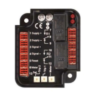
3.1.1 DC SUPPLY, OUTPUTS G-L
NOTE: For further details of module configuration, refer to DSE Publication: 057-237
DSE335 Configuration Software Manual.
Pin
No
Description
Cable
Size
Notes
1
DC Plant Supply Input
(Negative)
2.5 mm²
AWG 13
2
DC Plant Supply Input
(Positive)
2.5 mm²
AWG 13
Supplies the module and DC Outputs A, B, C, D, E & F
3 Output relay G
1.0 mm²
AWG 18
Plant Supply Positive from terminal 2. 2 Amp rated.
4 Output relay H
1.0 mm²
AWG 18
Plant Supply Positive from terminal 2. 2 Amp rated.
5 Output relay I
1.0 mm²
AWG 18
Plant Supply Positive from terminal 2. 2 Amp rated.
6 Output relay J
1.0 mm²
AWG 18
Plant Supply Positive from terminal 2. 2 Amp rated.
7 Output relay K
1.0 mm²
AWG 18
Plant Supply Positive from terminal 2. 2 Amp rated.
8 Output relay L
1.0 mm²
AWG 18
Plant Supply Positive from terminal 2. 2 Amp rated.
3.1.2 CONFIGURABLE DIGITAL INPUTS A-I
Size
Notes
9 Configurable digital input A
0.5 mm²
AWG 20
Switch to negative or positive depending on configuration
10 Configurable digital input B
0.5 mm²
AWG 20
Switch to negative or positive depending on configuration
11 Configurable digital input C
0.5 mm²
AWG 20
Switch to negative or positive depending on configuration
12 Configurable digital input D
0.5 mm²
AWG 20
Switch to negative or positive depending on configuration
13 Configurable digital input E
0.5 mm²
AWG 20
Switch to negative or positive depending on configuration
14 Configurable digital input F
0.5 mm²
AWG 20
Switch to negative or positive depending on configuration
15 Configurable digital input G
0.5 mm²
AWG 20
Switch to negative or positive depending on configuration
16 Configurable digital input H
0.5 mm²
AWG 20
Switch to negative or positive depending on configuration
17 Configurable digital input I
0.5 mm²
AWG 20
Switch to negative or positive depending on configuration