115
2009 DURATECH TUB GRINDER OPERATING INSTRUCTIONS
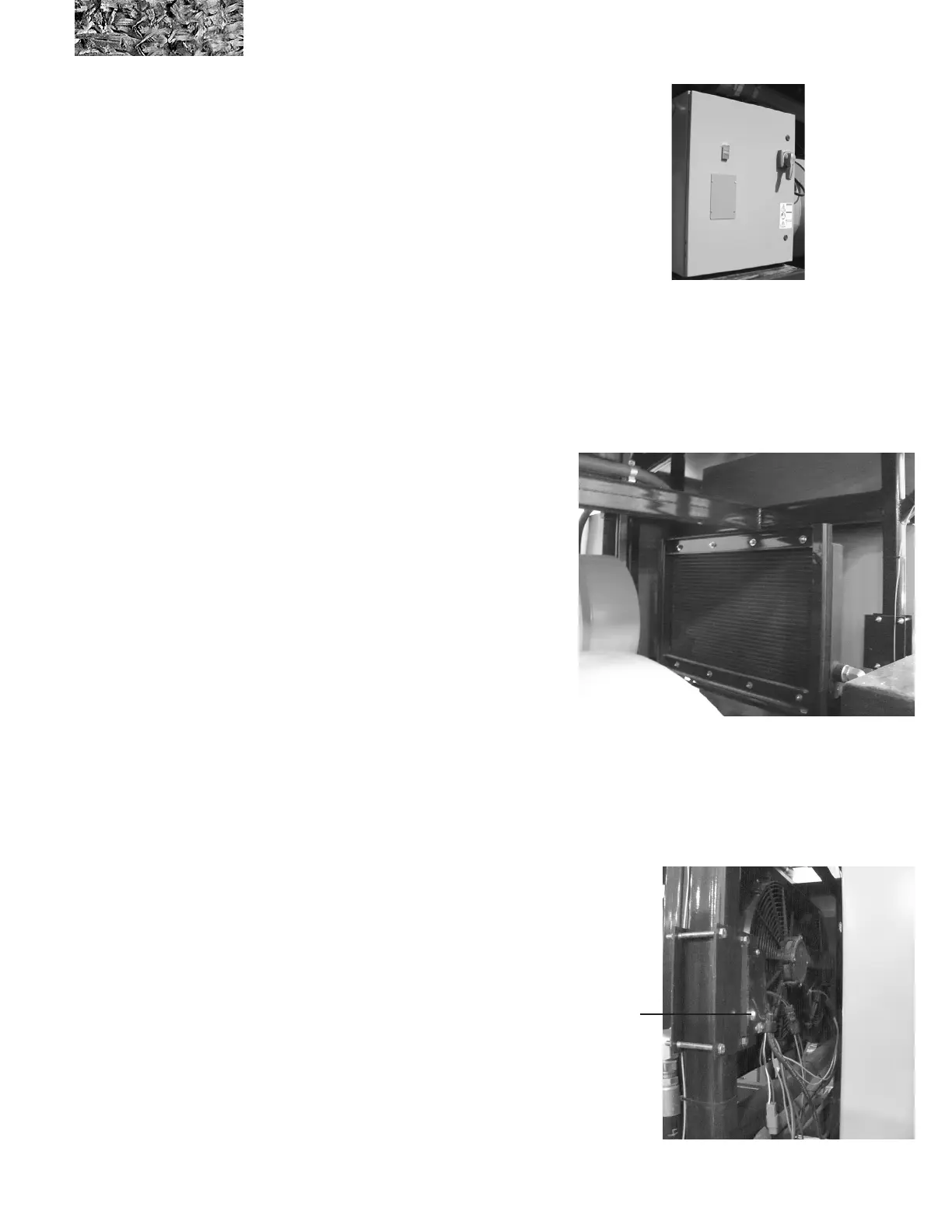
The 75Hp electric motor has its own soft start panel with
start and stop buttons on the front of it. At startup of the
grinder, it is recommended that the main electrical motor
be started rst and then the 75 Hp electric motor. This will
keep the amount of electricity used at initial startup down.
This motor can also run by itself during maintenance and
set up.
Supplement Section 5: Hydraulic cooler
The 2009EL electric grinder is equipped with DC motor driven hydraulic oil cooler to provide supplemental cooling of
the hydraulic oil. The fan on the cooler is driven by a DC electric motor. The fan on/off and direction is regulated by a
controller based on the oil temperature.
RED ERROR CODE LED BLINKS:
1 TIME = FAN “A” OVERLOAD
2 TIMES = FAN “A” OPEN
3 TIME = FAN “B” OVERLOAD
4 TIMES = FAN “B” OPEN
Explanation:
1,3 The controller is overheating. Either the fan
is drawing more current than it should, or the
controller is not being cooled sufciently.
2,4 The fan is not connected. Check for broken wires.
The minimum current draw must be 2A to keep the
system from showing an error.
Green LED
( REV. 10-13 )
The fans will start when the oil temperature reaches 125
degrees Fahrenheit (52 degrees Celsius). The fans will
stop and then reverse for 30 seconds when the temperature
reaches 170 degrees Fahrenheit (77 degrees Celsius). This
is an attempt to blow dirt of the cooler. Fans will then stop
and go forward. If the oil stays hot, the cooler needs to be
cleaned.
The controller has 2 LED’s which display the system
status. The green LED will light when power to the system
is applied and no errors are detected. The red LED will
blink if there are faults to the output (fan motor). The
output is monitored for no-load or overload conditions. If
a fault condition occurs, count the number of blinks of the
red LED, then refers to the error codes below:
Indicator LED’s
FAN “A” - HAS YELLOW (+) AND WHITE (-) WIRES.
FAN “B” - HAS GREEN (+) AND BLUE (-) WIRES.