66
2009 DURATECH TUB GRINDER OPERATING INSTRUCTIONS
5.10 Rotor bearing installation (For S.N. up to 064)
WARNING: To ensure the rotor is not unexpectedly started, turn off and lock out or tag the power
sources before proceeding. Failure to observe these precautions could result in bodily injury.
NOTE: Bearing housing caps and bases are not interchangeable and must be matched with mating
half. Install the non‑expansion bearing rst.
1. Apply a light coating of oil or other rust inhibitor to the adapter area of the shaft.
2. Measure the internal clearance of the bearing before mounting. Place the bearing in an upright position.
Seat the inner ring and roller elements by pressing down rmly on the inner ring bore while rotating the
inner ring a few times. Position the roller assemblies so that a roller is at the top most position on both
sides. Using a feeler gauge measure the clearance on both sides of the roller by inserting the feeler gauge
as far as possible and sliding over the top of be roller. Write down the measured clearance for use in step
3E.
NOTE: Do not rotate bearing when the feeler gauge is between the roller and the outer ring.
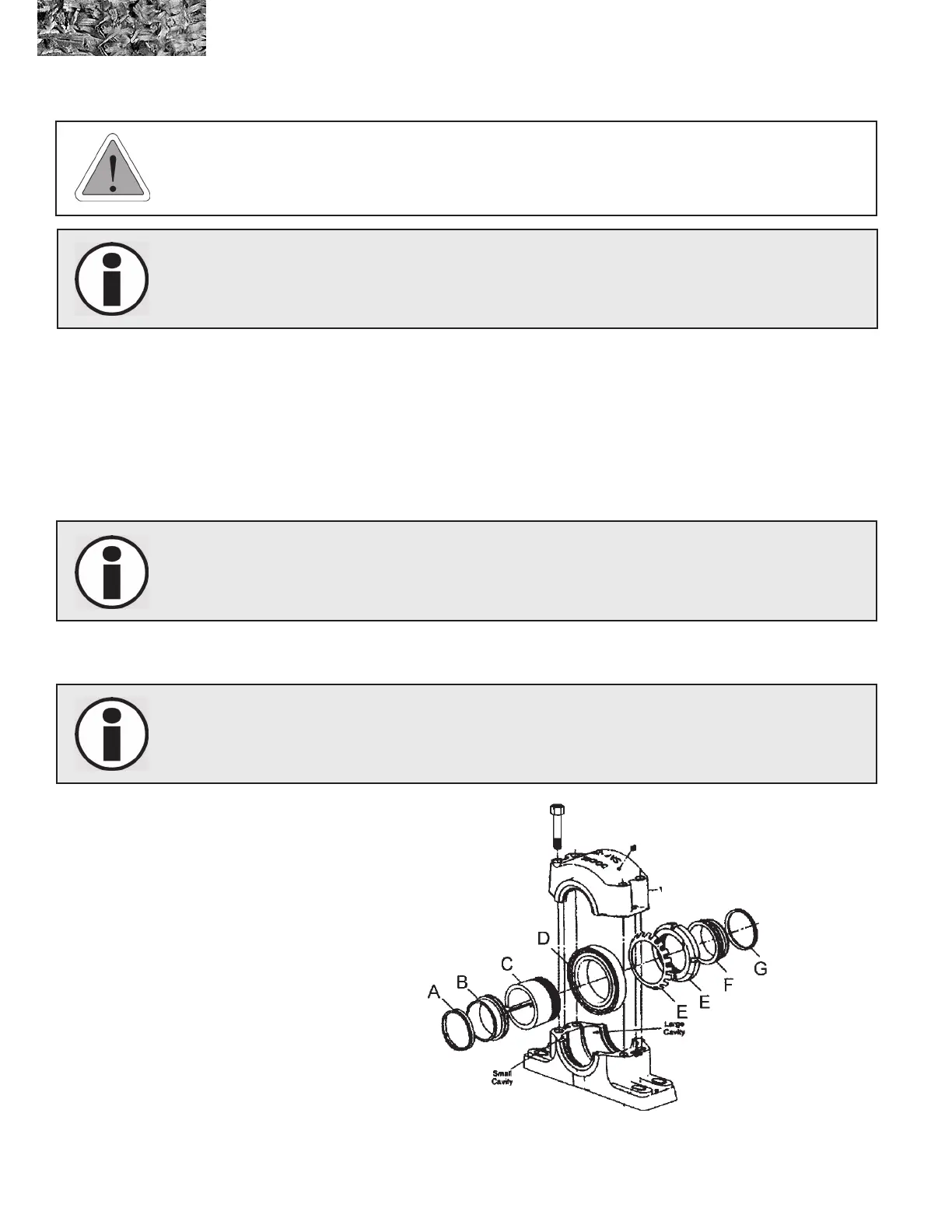
3. Install the bearing parts in the following sequence.
NOTE: There is only one way to correctly install the bearing. Refer to Figure below for illustration.
NOTE: Large cavity of
Pillow Block Housing
must be on the same
side as knockout.
( REV. 09-17 )