70
2009 DURATECH TUB GRINDER OPERATING INSTRUCTIONS
MOUNTING
Install the non expansion unit rst.
1. Apply a coating of light oil or other rust inhibitor to
the adapter area of the shaft.
2. Before mounting bearing to shaft, remove
lockplate from bearing and turn locknut
counterclockwise one to two turns to allow adapter
to expand fully. The unit is now shaft ready. Slide
the bearing to the desire position on the shaft.
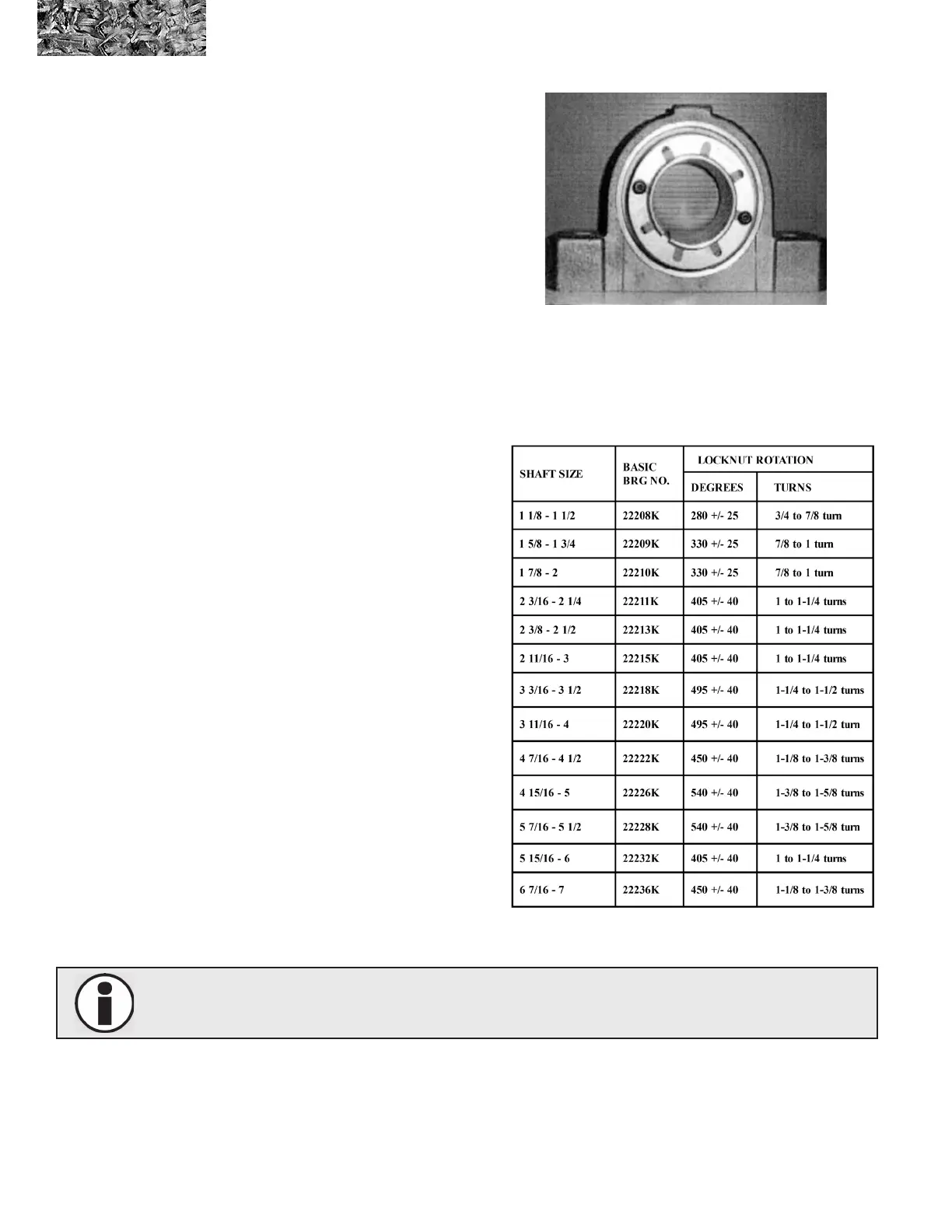
3. Proper locking of this unit to the shaft is based
on turning the locknut clockwise a predetermined
number of degrees shown for each bore size on
Table 1. The turning of the locknut must start from
a “ZERO reference point.” This “ZERO reference
point’ is dened as the point when the clearance
between adapter sleeve, shaft and bearing bore
has been removed, and all surfaces are in metal to
metal contact
3A. To reach the ‘ZERO Reference Point,” rotate
locknut clockwise, using both hands, as tight as
possible When mounting bearings with shaft sizes
3 15/16” and larger the following TEST must be
performed. As a test to insure you have reached
the “ZERO Reference Point” tap on the face of the
nut with a hammer and attempt to rotate the nut
using both hands
If the nut will not rotate then you
have reached the ‘ZERO Reference Point’ and you
should proceed to step 4. if you can rotate the nut,
using both hands, then you have not reached the
true ‘ZERO Reference Point,” and should repeat
step 3A until ‘ZERO Reference Point” is obtained.
NOTE: All Weight Must Be Removed From The Bearing When Obtaining The “ZERO Reference
Point.”
Picture 1