6 INSTALLATION
Refer to Installation and Operation Manual
7 MODES OF OPERATION
7.1 NORMAL MODE
In each mode description, the serial mode commands (CameraLink and LVDS versions only)
are shown. Please refer to the serial mode commands details in Section 9.4.
NRR: Normal mode with reset
NOR: Normal without reset
In the normal mode of operation, the following signals are used to synchronize a digital frame
grabber to the camera:
Pixel Clock
: Periodic 18 MHz, square wave output which is synchronous with digitized pixel data.
Enable Frame
: Periodic 10 Hz (frame rate) output; the rising edge signifies the start of a valid
frame and the falling edge signifies the end of a valid frame
Enable Line
: Periodic 10.7 KHz (line rate) output; the rising edge signifies the start of a valid line
and the falling edge signifies the end of a valid line.
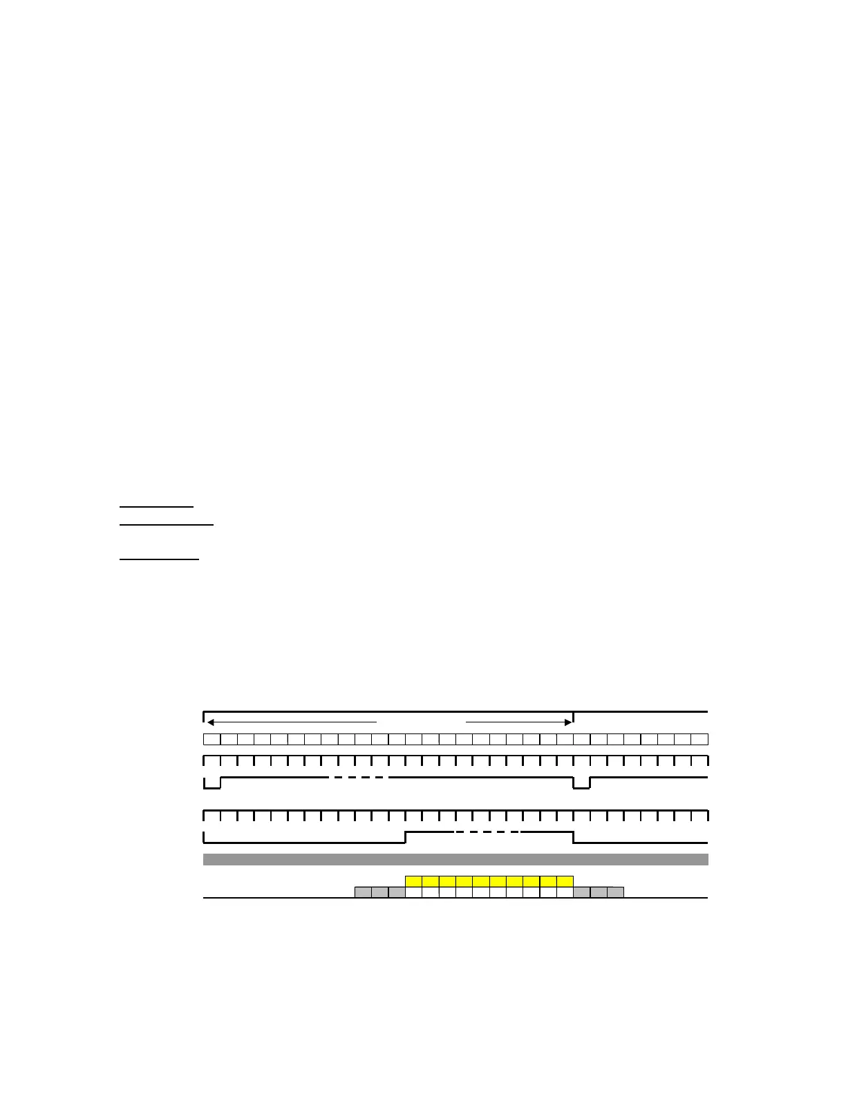
The Horizontal and Vertical Drive signals are usually outputs generated by the camera.
In the timing diagram show below, charge transfer from the active (imaging) charge sites to
adjacent (opaque) storage sites takes place at the beginning of a frame. In this process, all the
charge that was accumulated in the imaging charge sites during the previous frame is transferred to
the opaque storage sites.
Charge transfer
Line count
1
2
3
4
5
6
7
8
9 10 11 12 13 … … … 1047 1048 1049 1050 1051 1052 1 2
3
4
5
6
7 ....
Horizontal Drive
Vertical Drive
Enable Line
Enable Frame
Pixel Clock
V I D E O
CCD Output
BLK BLK BLK 1 2 .... .... .... .... … … … 1030 BLK BLK
BLK
Exposure = 1/10 sec
Figure 7.1-1: Timing diagram--normal mode
16