invoked with an increment of 120 frames = 12 sec. The transition between NFR mode and ULT
mode may be transparent to the user; the only real difference between the ULT and NFR mode
from the user’s perspective is the “granuality” of control.
7.5 PULSE DRIVEN EXPOSURE
PDX: Pulse driven exposure (external)
PDI: Pulse driven exposure (internal, one-shot)
PDP: Pulse driven exposure (internal, periodic)
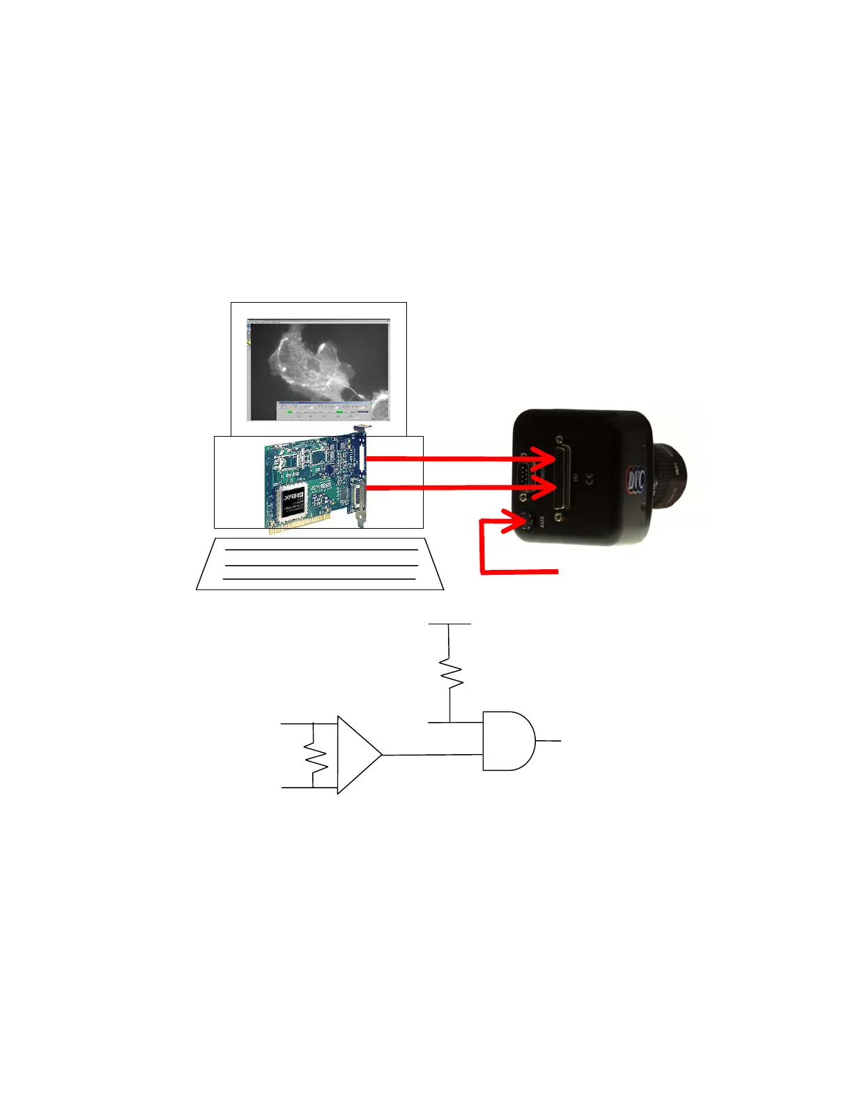
INPUT 1 –
CC1+ / INPUT 1 +
CAMERA RESET
(INTERNAL SIGNAL)
VRST_INT
(TTL)
+ 5V
(LVDS differential input
from frame grabber board)
VRST_INT (TTL)
INPUT 1 +
CC1- / INPUT 1 –
Figure 7.5-1: Asynchronous Reset
When the Pulse Driven Exposure mode is selected, the duration of exposure is set by the user via
the LOW duration of an externally generated pulse. A falling edge of the pulse clears the imager
and initiates exposure, a subsequent rising edge terminates exposure, resets the vertical counter
within the camera and initiates readout of the acquired frame.
This pulse signal may be TTL (VRST_INT) or differential(CC1+ or CC1-) or (INOUT1 + &
INOUT1-); these two inputs are logically AND-ed within the camera, therefore one of them should
normally be HIGH if the other one is to be used. There are no prescribed limits to the LOW
duration; therefore this mode affords the user the most flexibility in terms of controlling the
23