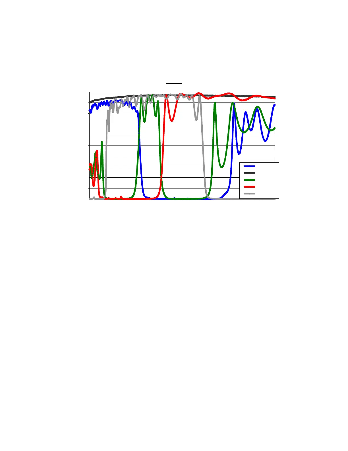
7.10.2 Spectral Response
NOTE: the spectral response curves shown represent the R, G, B, clear configuration of the filter-
set. Since the camera design allows the user to insert any filter-set of choice, this data may not be
valid for user-configured cameras.
Filters
0
10
20
30
40
50
60
70
80
90
100
950900850800750700650600550500450400350
Wavelength (nm)
% Transmission
Blue
Clear
Green
Red
IR
7.10.3 Module Removal & Change of Filters
Estimated Time of Removal: 2-3 minutes
Materials Needed: 3/32" socket head drive, dry air bottle
Important Considerations:
• Use care not to put fingerprints on the filter surfaces. Wear rubber gloves while
performing this operation
• Filters with holders & glass thickness up to 5mm are acceptable in 25 mm diameter
aluminum frame
• The housing that holds the filter should be 3.5mm - 5.5mm thickness and 25.4mm in
diameter.
• For RGB, the filter disk is numbered 1C, 2R, 3G, 4B (where C = Clear, R = Red, G =
Green, B = Blue). The filters must be placed in this order
• When the camera is turned on, it will set itself such that, position 1 is the default or home
position in front of the lens
35