duration and the instant of exposure. For example, application software can be written to directly
drive the camera between long and short exposures without any latency; some application
developers choose to use the PDX mode as the sole camera mode, since this can control long and
short exposure easily by controlling a single signal. The max rep rate of the driving pulse in the
1412 is limited to 1/(frame period + exp).
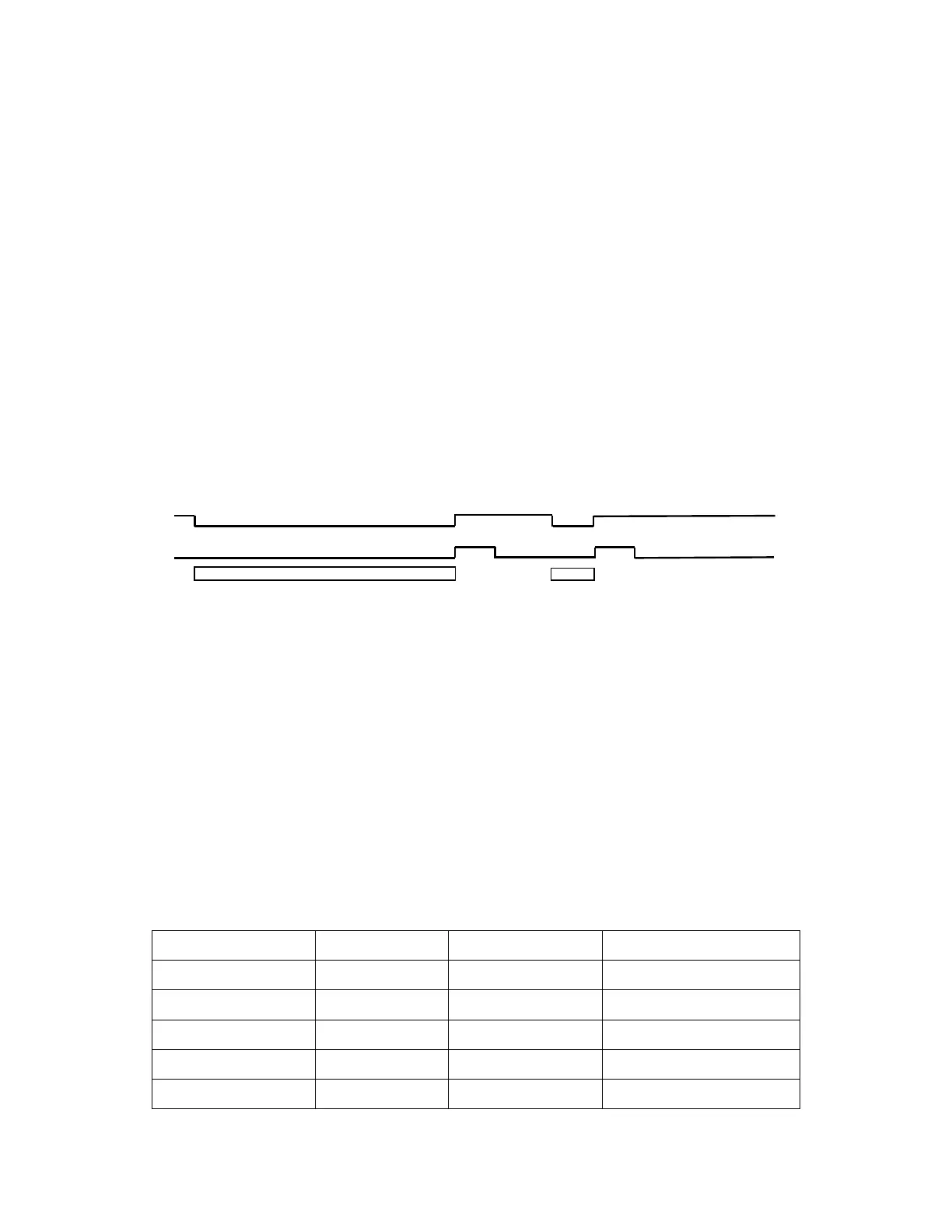
In order to maintain synchronization with a frame grabber, the pixel clock and enable line signals
are un-interrupted during exposure and subsequent readout. The enable frame signal, however, is
set "low" during exposure and goes "high" only during readout to signify that the accumulated
frame is being read out and may be captured by the frame grabber. This is shown graphically in the
timing diagram below.
NOTE: The frame grabber should be capable of sustaining long periods of time without receiving
an Enable-Frame signal.
PDI and PDP are special cases of the Pulse driven exposure mode, in which the camera
microprocessor is used (via the TIL & TIH cmd) to drive the reset pulse. These modes are of
limited use except when the frame grabber does not have a well defined method of generating
exposure pulses.
Pulse Driven Integration Mode
ENABLE FRAME
INTEGRATION PERIOD
VRST_INT (TTL) or INOUT1 (LVDS)
1/10 sec
1/10 sec
INTEGRATION
PERIOD
Figure 7.5-2: Pulse driven integration mode, showing long/short exposure with minimum latency
7.6 BINNING
Binning is a feature of the camera that allows the user to trade-off camera resolution in favor of
frame rate and sensitivity. When one of the binning modes is selected, a selected number of
contiguous pixels is treated as one “super-pixel”. This is illustrated below, shown in the bin 2x2
case. By means of transferring two lines into the horizontal shift register, pixels are summed
vertically. These vertically summed pixels are then clocked out to the detection mode without the
usual intervening reset gate signal.
Table 7.6-1: Binning commands
Command Code Description Frame Size Frame Rate
BIN 11 1 x 1 binning 1392(H) x 1040(V) 10.2f/sec (normal mode)
BIN 21 2 x 1 binning 1392(H) x 520 (V) 20f/sec
BIN 22 2 x 2 binning 696(H) x 520(V) 20f/sec
BIN 44 4 x 4 binning 348(H) x 260(V) 39f/sec
BIN 88 8 x 8 binning 174(H) x 130(V) 68f/sec
24