47 / 84 SM-SG-2 Ev3/25062014
6.17 REPLACEMENT OF THE WHEEL SUSPENSION ARM
Dismounting:
- Lift the mower (the wheels must be at least 150 mm off the ground)
- Remove the wheel suspensions
- Remove the belts and corner brackets see 6.15 Replacement of the driving belts
- Remove the stabilizer
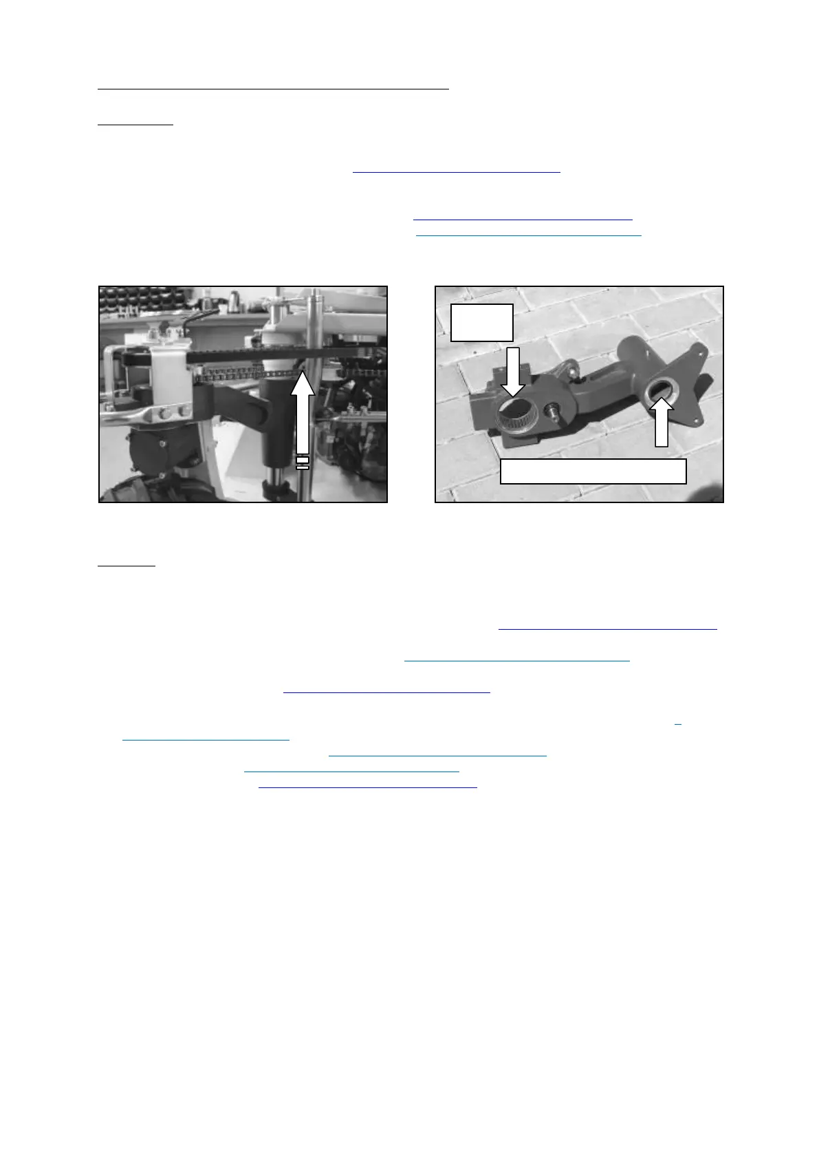
- Release the chain tension adjuster
- Remove the steering clamp bushings-taper locks see 6.23 Adjustment of the wheel geometry
- Remove the cross, girder and stabilizer stiffeners see 6.26 Replacement of the girder and cross
- Remove the arms
- Remove the rollers from the arms and the pull rod from the ball journal
Fig. 95
Fig. 96
Mounting:
- Lubricate the guide bushings (MOBILGREASE XHP 222) and slide in the arms
- Mount the rollers onto the arms (MIND the distance ring under the rollers)
- Install the stabilizer ball joint
- Install the taper locks on the steering shaft and tighten smoothly see 6.23 Adjustment of the wheel geometry
- Slide on spring and the extension piece
- Install the cross, girder and stabilizer stiffeners see 6.26 Replacement of the girder and cross
- Install the wheel suspensions
- Install the corner bracket see 6.15 Replacement of the driving belts
- Use the grease nipples to lubricate the arms (MOBILGREACE XHP 222), wheel segment, guide bushing of
the cross (Interflon FIN LUBE TF) and grease the needle bearing with the steering transmission see 4
Regular maintenance SPIDER
- Adjust the length of the pull rods see 6.21 Adjustment of the stabilizer length
- Tension the chain see 6.13 Replacement of the steering chain
- Adjust the geometry see 6.23 Adjustment of the wheel geometry
- Test the driving, lift and turning the mower wheels