61 of 105
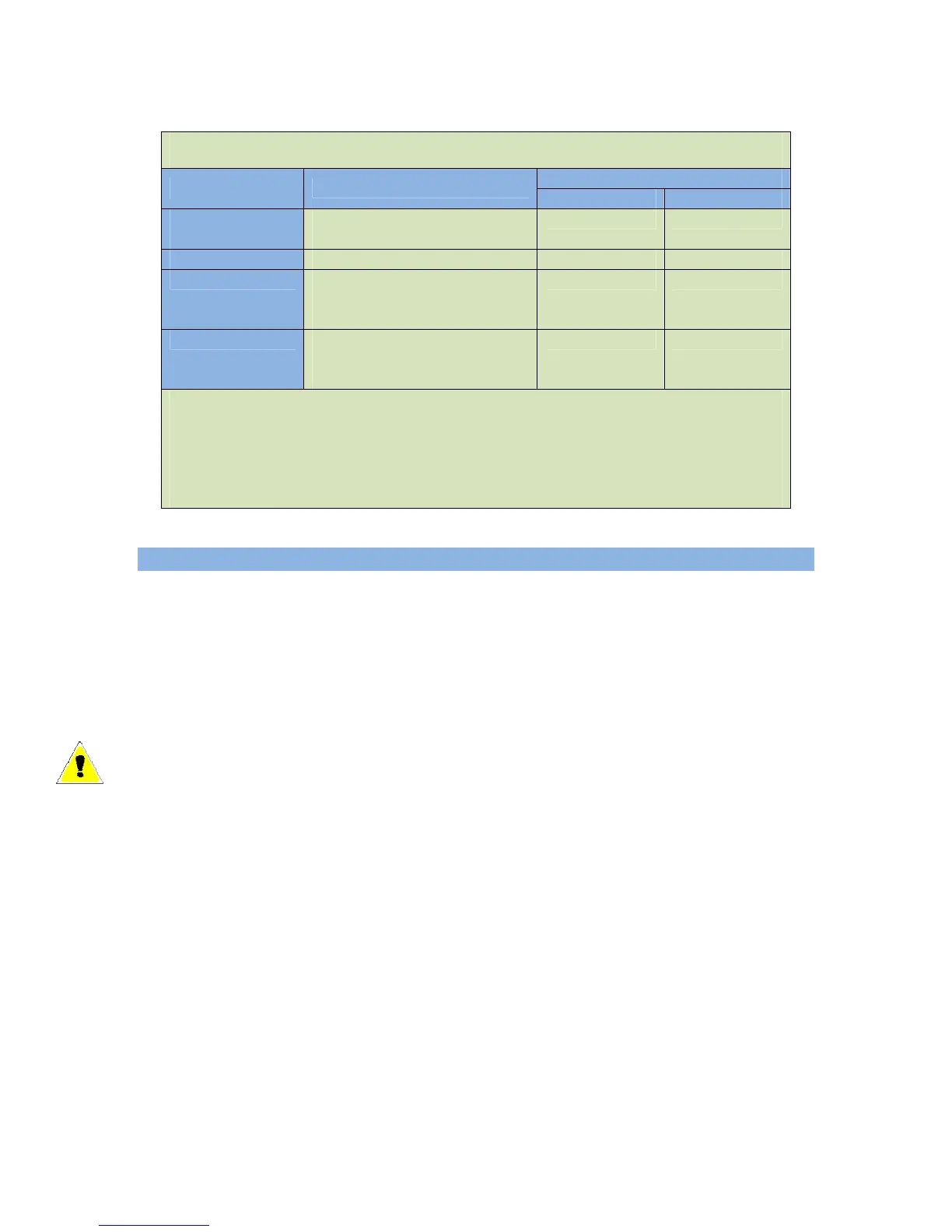
Table 13 Voltage Select Inputs
Digital Inputs
Voltage Configuration
Volt Select 1 Volt Select 2
Voltage Group 1 1 Phase, 3-wire (2-wire option
(Single Phase) also selectable)
Open Circuit Open Circuit
Voltage Group 2 3 Phase, 4-wire Wye ACTIVE
Open Circuit
Voltage Group 3 3 Phase, 4-wire
(2x display voltage option also
selectable)
Open Circuit ACTIVE
Voltage Group 4 3 Phase, 4-wire Wye
(4-wire Delta option also
selectable)
ACTIVE
ACTIVE
If Digital Input Pin A, B, C or D is used, then ACTIVE is defined as a switched to
+BAT connection. If Digital Input Pin E, F, G or H is used, then ACTIVE is defined as a
switched to GND connection.
NOTE: If only a single AC Group Sel function is selected, then the remaining
unassigned AC Group Sel is equivalent to an “Open Circuit” in the above table.
6.4.3 AC Current
The GSC400 controller is designed to measure AC current from the generator with the
use of current transformers (CTs). The maximum current on the AC current terminals of
the GSC400 is limited to 5A.
e CT ratio. All numbers in this menu are
1000:5A which, in turn, means the
The
hese a The current warning and failure
e
eter (second to last entry in the AC Current menu) is used to
ng (50% selection). If this is not desired then the 100% selection
e
off by the user
The “Turns Ratio” sub menu is used to setup th
in terms of 5A. For example select 1000 means
GSC400 displays 1000A on the screen when the current measured on the GSC400 AC
Current terminals is 5A. The GSC400 current terminals can handle a maximum of
5A. a L rger currents can damage the GSC400.
AC Current menu is also used to set the over current warnings and shutdowns.
re grouped in terms of the voltage group 1 to 4.T
depends on the voltage group selected in the Voltage Group submenu of the AC Voltag
menu.
The Hi Wye Current param
double the current readi
should be selected. Some generators have two wires for each phase, and as such, the
current transformer (which is placed on one lead) will see only 50% of the current from
each phase.
The Cur Warn Latch option (last entry in the AC Current menu) is used to latch on a
special digital output (see Current Latch in Table 14 on page 64) that turns on when th
current exceeds the Current Warning Threshold and can only be turned
 Loading...