78 of 105
9 Appendix A: Accessory List
9.1 GSC400 Controller Harness - Accessories
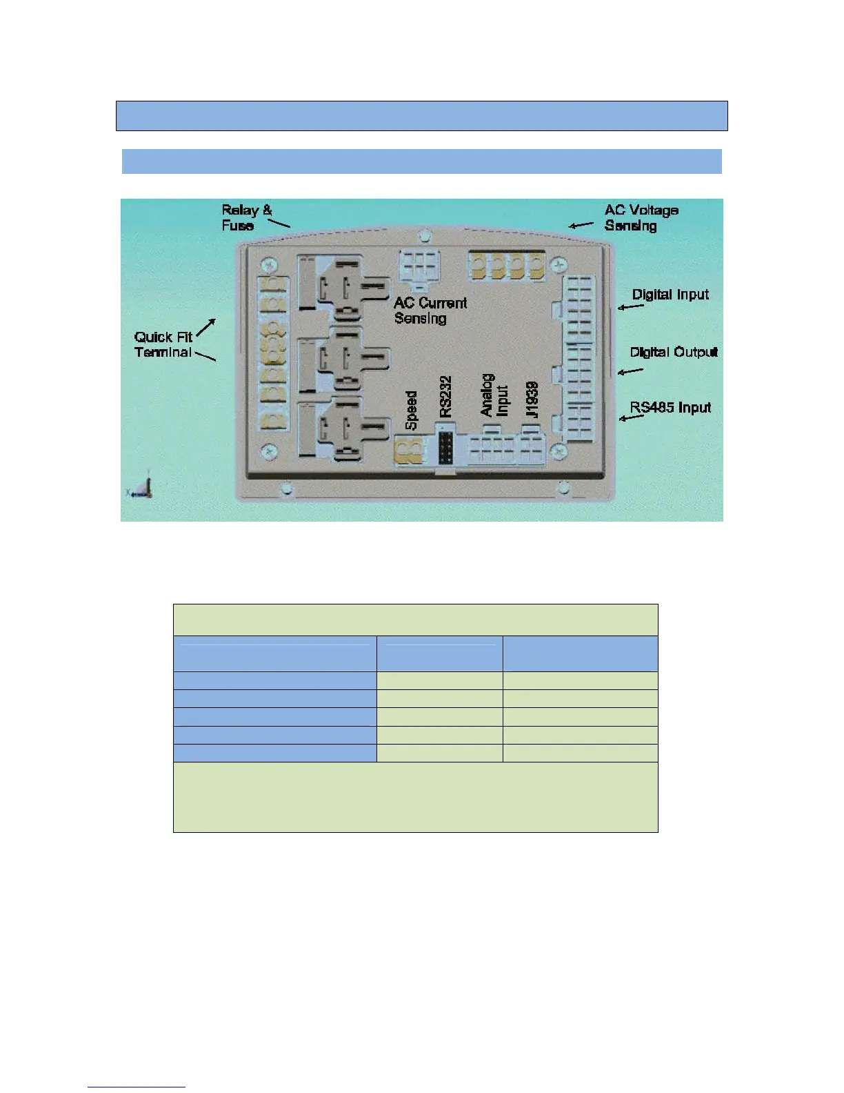
Figure 11 – GSC400 terminal names and layout. View from rear of controller.
Table 18 – GSC400 Harness Part Numbers
Harness Name 5ft Harness
Circuit Numbers
(Pins) Populated
CAN (J1939) (Rev 3) 1373R3-5 1, 2, 3
1
AC Current Sensing (Rev 2) 1375R2-5 All circuits
Digital Outputs (Rev 2) 1377R2-5 1, 2, 3, 4
Analog Inputs (Rev 2) 1376R2-5 1, 2, 3, 4
Digital Inputs (Rev 2) 1378R2-5 4, 7, 8, 9*, 10, 11, 12*
1
The new Rev 3 of this harness contains a terminating resistor. If the
GSC400 is not the last device on the network this resistor can be cut out.
*Circuits 9 and 12 are tied together. This disables the emergency stop input.
For users who desire this feature cut this wire.
 Loading...