•
•
•
•
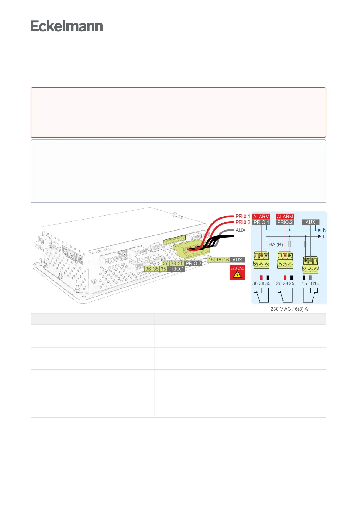
7.1.3 Terminal assignment of the 230 V relay outputs
The two relay outputs PRIO1/PRIO2 can be used for sending alarms with these priorities. The multifunctional
relay AUX can be freely configured (see table). The terminals are located at the bottom on the device.
Terminal No. Function
36 (closed in the alarm state)
38 (open in the alarm state)
35 (common)
Alarm relay PRIO1: Alarm for messages with priority 1 (PRIO.1)
26 (closed in the alarm state)
28 (open in the alarm state)
25 (common)
Alarm relay PRIO2: Alarm for messages with priority 2 (PRIO.2)
15 (common)
18 (normally open contact)
16 (normally closed contact)
Multifunction relay AUX: can be configured using Menu 4-1-7 as
horn
additional alarm relay with the priority PrioX3, PrioX4, PrioX5, PrioX6,
PrioX7, PrioX8 or PrioX9
modem hardware reset,
or
for switching the modem to the DDC (T-connector required)
Fordetailsabouttheconfiguration,seechapterRelay outputs.
DANGER
Warning about dangerous electrical voltage! Danger of electric shock! BEFORE connecting and
disconnecting, it must be checked that no voltage is presentatthe230VACrelayoutputs!Low
voltage and safety extra-low voltage must not be applied together at the relay outputs 15/16/18,
25/26/28 and 35/36/38.
•
•
In order to fuse the supply line and relay outputs, a circuit breaker with the following characteristics
must be used for each relay output:
Rated current for 230 V AC: 6(3) A
Tripping characteristic (typical): B
If the alarm signalling is carried out using a telephone dialling device using the provided OFF-delay
alarm contacts PRIO1/PRIO2, these must be subjected to cyclical monitoring to ensure that the
contacts also still signal in the event of power failure.