•
•
•
•
•
•
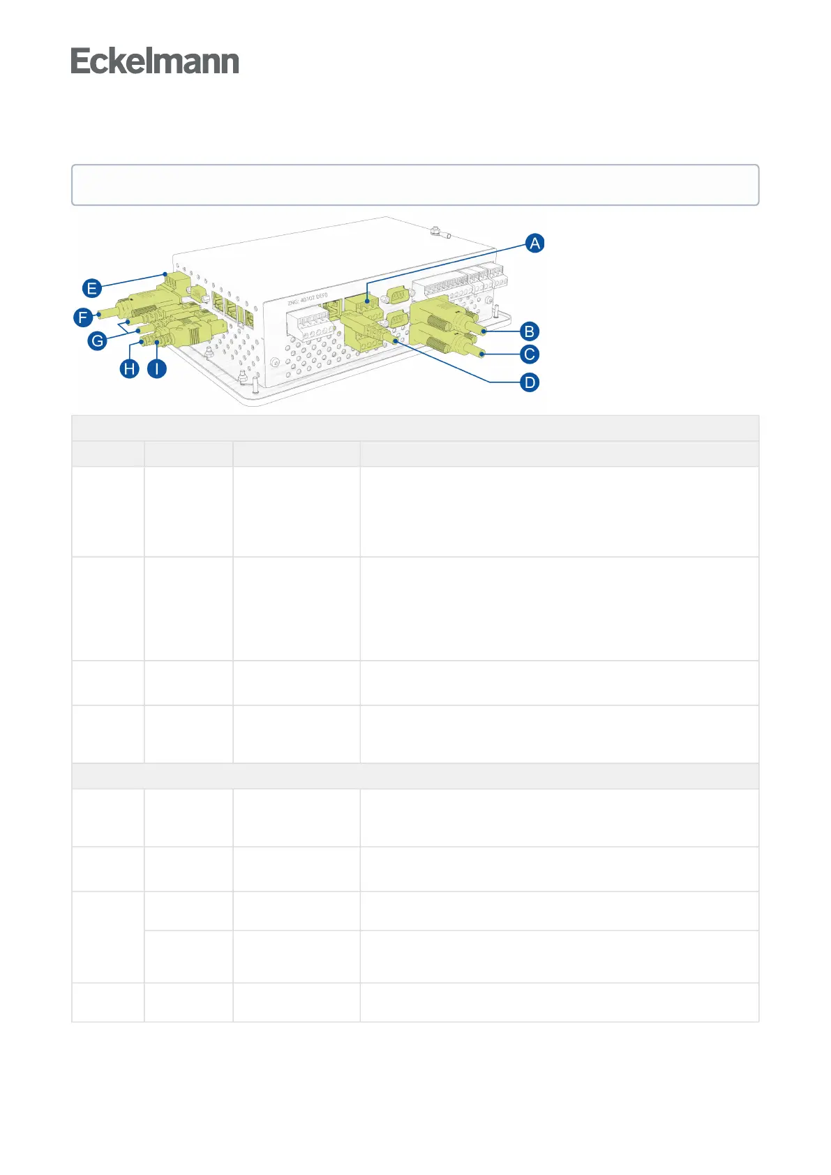
7.1.7 Terminal assignment of communication interfaces
Interfaces at the bottom on the device
Interface Designation Type Function
A CAN bus CAN1 and CAN2
COMBICON terminal
blocks
Connection of the system centre to
the first CAN bus segment via CAN1,
the second CAN bus segment via CAN2 (CAN2 only for VSC 5510 /
VSC 5110).
For details, see chapter Terminal assignment of the CAN bus terminals.
B COM1 /
MODEM
RS232
Sub-Min-D (male)
For connection
of a null modem cable for the connection of the PC software LDSWin
or
of a modem.
For details, see chapter Configuration of the E*LDS system using Service PC
on-site.
C COM2 RS232
Sub-Min-D (male)
M-bus
For details, see chapter M-bus interface for consumption data capture.
D SIOX data cable RJ45 female connector Data cable for SIOX extension modules
ATTENTION: DO NOT connect using the Ethernet/LAN network cable!
For details, see chapter SIOX - connection to the system centre
Interfaces on the left on the device
E COM3/
MODBUS
RS485
COMBICON terminal
block
For the connection of UA 30 / Dixell controllers and LDS1 gateways.
For details, see chapter Terminal assignment of the COM3 / MODBUS
terminals (RS485).
F COM4 RS232
Sub-Min-D (male)
For the connection of external controllers (Danfoss AHT / Wurm AHT)
For details, see chapter Integration of external controllers.
G ETHERNET/
LAN 2
RJ45 female connector Ethernet / LAN interface for the connection of a controller of the Virtus LINE,
e.g. VPC 5000.
ETHERNET/
LAN 1
RJ45 female connector Ethernet / LAN interface for the connection to the Intranet / Internet via VPN
router (PC software LDSWin and for Remote control via Virtus Control Desk
(VCD)).
G USB - Host USB 1.1 female
connector A
For plugging in a USB stick for a firmware update;
for details, see chapter Firmware Update.
The functions of the communication interfaces are configured in Menu 4-1-5.