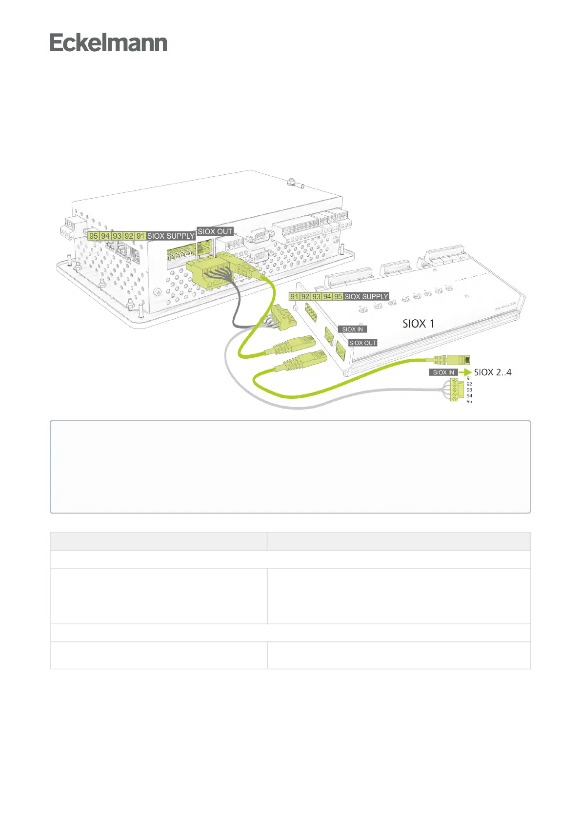
7.1.5 Terminal assignment of the SIOX interfaces
The interfaces for the connection of up to 4 SIOX extension modules to the system centre are located on the
device at the bottom. The number (1..4) of extension modules is defined in Menu 4-1-1. With each additional
SIOX, the system centre is extended by 12 digital inputs (e.g. for system monitoring or for energy meters) and 8
relay outputs (e.g. week timers or for load shedding).
Terminal No. Function
Power supply - SIOX SUPPLY *
91
92
93
94
95
Ground of 9 V
+9 V DC
Ground of 24 V
+24 V DC
SHLD (shield)
Dataport-SIOXOUT*
RJ45 female connector Data cable output for the connection
of the first SIOX extension module
*Recommendation: SIOX supply cables and SIOX data cables are available as accessories for the
connection,seechapterZubehör für Systemzentrale.
ATTENTION
Danger of destruction of components! SIOX extension modules may only be connected to each
other or the system centre when no voltage is present! In the event of an Ethernet network cable with
PoE (Power over Ethernet) being used instead of the SIOX data cable (RJ45) damage can occur to
participating network devices! Only components approved by Eckelmann AG may be connected to the
SIOX extension bus (terminals SIOX OUT / SIOX IN or terminals 91..95)!