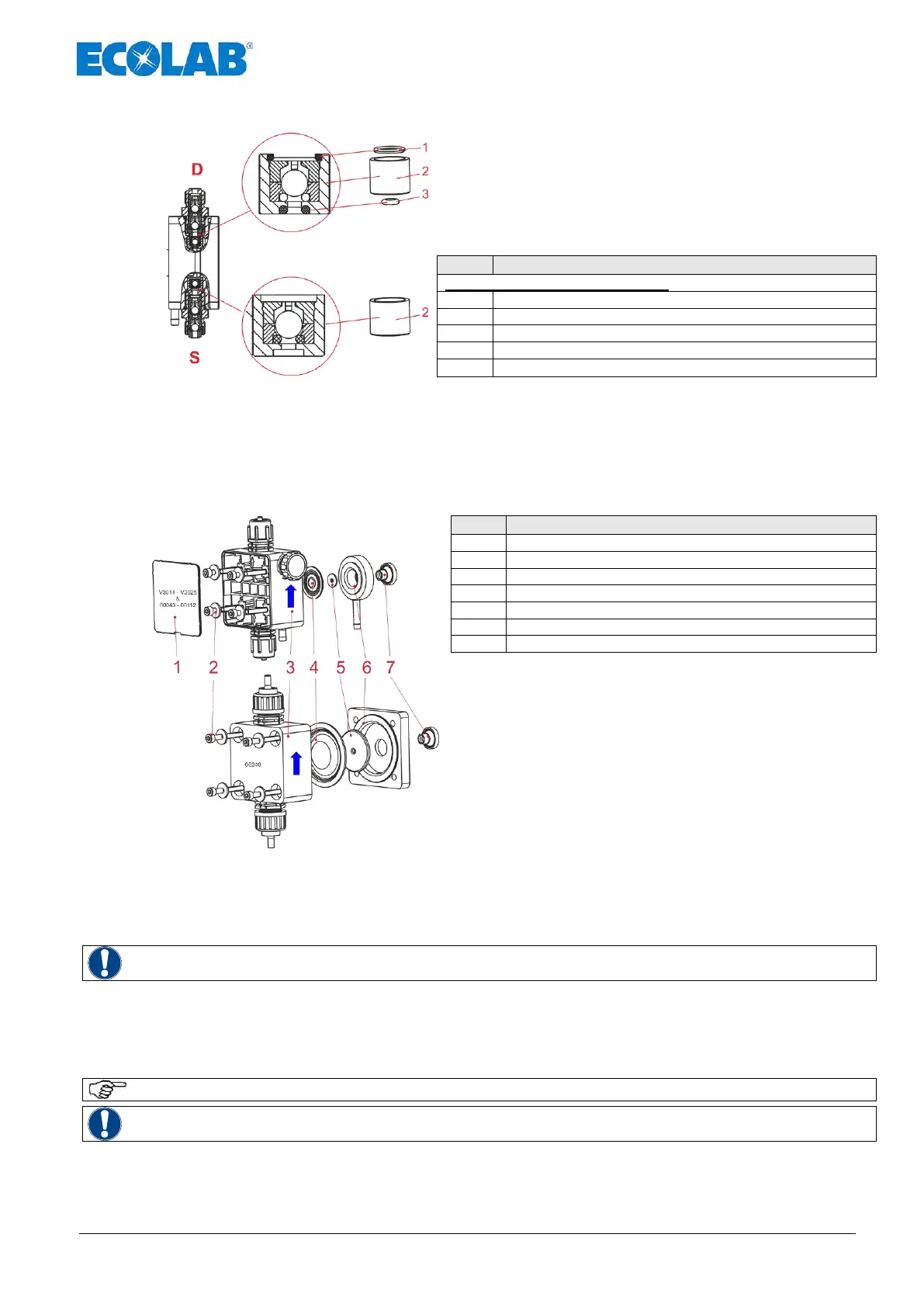
8.1.3 Changing the valve cartridges (only type V3014 and V3025)
When replacing the V3 valve cartridges, ensure that
they are inserted in the correct position.
The small O-ring (Pos. 3) must be inserted so that it
points downwards (in the direction of the pump head)
upper valve cartridge consists of:
Pressure side -> Pressure valve
Suction side -> Suction valve
The lower valve cartridge is inserted without O-rings. However, its location corresponds to the
upper valve cartridge. Therefore, the groove must point in the direction of the pump head in
which the large O-ring (Pos. 2) would fit.
8.2 Replacing the diaphragm and pump head
Metering head screws (4 x)
Supporting disk (not for 2.5 l/h)
Remove cover plate (Pos. 1) on the metering head
Loosen the metering head screws (Pos. 2).
Remove the pump head (Pos. 3).
Unscrew the diaphragm (Pos. 4), sandwich plate
(Pos. 6) and supporting disk (Pos. 5).
Pull the bellows (Pos. 7) off the push rod.
Insert the new bellows in the correct position
(see illustration).
Insert the sandwich plate in the correct position (see illustration).
Slide the supporting disk in the correct position (curved side in the direction of the
diaphragm) over the thread of the diaphragm.
Insert the new diaphragm with the supporting disk.
Only screw in the diaphragm by hand. (Do not use a tool!)
Turn the sandwich plate clockwise until the diaphragm breakage outlet points downwards
Affix the pump head (observe the flow direction, see Fig. 8.6)
Screw in the pump head screws by hand
Tighten the pump head screws alternately on the right and left sides
Torque of the metering head screws = 3 - 4 Nm.
Check the torque of the metering head screws after 24 hours!
Fit the cover plate to the pump head.

 Loading...


