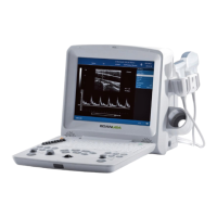
DUS 60 Digital Ultrasonic Diagnostic Imaging System User Manual Installation Instructions
- 18 -
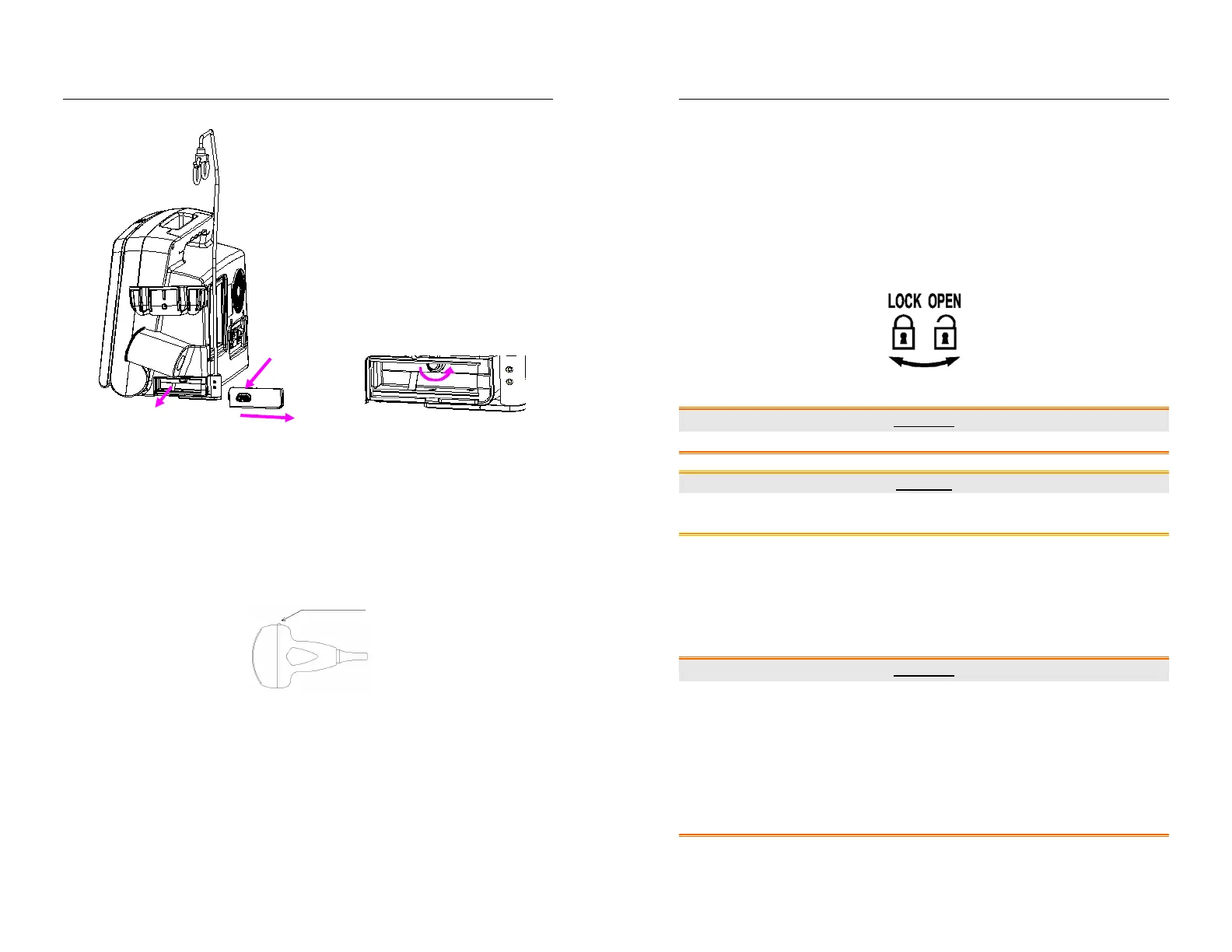
Figure 4-4 Uninstalling Battery from Main Unit
4.3.3. Connecting and Disconnecting Probes
NOTE:
Ensure that the system is shut down before connecting and disconnecting probes.
Flip images horizontally to change the scan direction or vertically to change the image orientation.
The scan direction mark located at the side of
probe indicates the beginning direction of scanning.
The scan direction mark is shown below.
Figure 4-5 Probe Scan Direction Mark Schematic Diagram
There is information about Model and SN on the probe connector.
To connect a probe:
1. Place the probe’s carrying case on a stable surface and open the case.
2. Carefully remove the probe and unwrap the probe cable.
3. Do not allow the probe head to hang free. Impact to the probe head could result in irreparable
damage.
Scan Direction Mark
①Press the button
②Pull the battery cover out
③Pull the flicker counterclockwise to hide it
④Pull out the battery
DUS 60 Digital Ultrasonic Diagnostic Imaging System User Manual Installation Instructions
- 19 -
4. Turn the connector locking handle to the OPEN position.
5. Align the connector with the probe port and carefully push into place.
6. Turn the locking handle on the probe connector clockwise to LOCK position. This ensures
the connector in position and ensures the best possible contact.
7. Place the probe in the probe holder.
To disconnect a probe:
1. Turn the locking handle on the connector housing counterclockwise to the OPEN position.
2. Firmly grasp the probe connector and carefully remove it from the system port.
3. Store each probe in its protective carrying case.
Figure 4-6 Lock and Open Marks on Probe Connectors
WARNING
Do not touch the pin of probe connector.
CAUTION
Do not plug in or pull out the connector when the device is activated. This is to avoid
uncontrollable damage to the probe and the main unit.
NOTE:
Once the probe is connected to the main unit, please do not reinstall it frequently. This is
to avoid poor contact between the probe and the main unit.
4.3.4. Peripheral Connections
Video connections are located on the left panel of the DUS 60.
WARNING
Accessory equipment connected to the analog and digital interfaces must be certified
according to the respective IEC/EN standards (e.g. IEC/EN 60950 for data processing
equipment and IEC/EN 60601-1 for medical equipment). Furthermore, all configuration
shall comply with the valid version of the standard IEC/EN 60601-1-1. Therefore,
anybody, who connects additional equipment to the signal input or output connector to
configure a medical system, must make sure that it complies with the requirements of the
valid version of the system standard IEC/EN 60601-1-1. If in doubt, consult our technical
service department or your local distributor.