DUS 60 Digital Ultrasonic Diagnostic Imaging System User Manual System Overview
- 10 -
Chapter 2 System Overview
2.1. Appearance
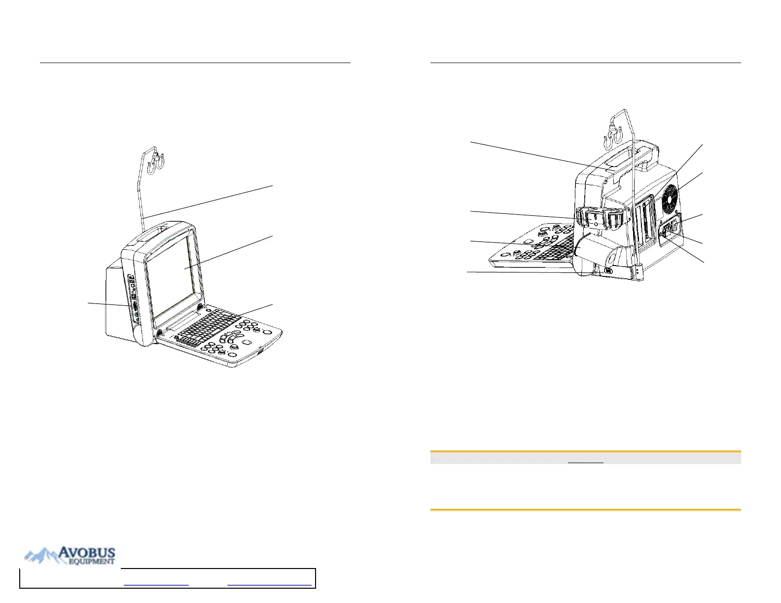
2.1.1. Front View
Figure 2-1 Front View
1. Cable holder
2. Display screen
3. Control panel
4. I/O ports
1
6
4
1
2
3
DUS 60 Digital Ultrasonic Diagnostic Imaging System User Manual System Overview
- 11 -
2.1.2. Rear View
Figure 2-2 Rear View
1 Probe sockets
2 Air Fan
3 AC power switch
4 Appliance inlet
5 Equipotential terminal
6 Handle
7 Probe holder
8 Coupling gel trough
9 Rechargeable lithium battery
CAUTION
1. To have good aeration performance and be able to operate normally, please don’t
cover or plug the air fan or heat dissipation orifice partly or wholly by using any object.
2. For easy control, please don’t cover or block the AC power switch using any object.
7
8
6
1
2
3
4
5
6
7
8