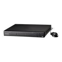
1, 2, …, 8. It becomes valid in low voltage.
485 communication port. They are used to control devices such as
PTZ. Please parallel connect 120Ω between A/B cables if there are
too many PTZ decoders.
3.7.2 Alarm Input Port
Please refer to the following sheet for more information. See Figure 3-3.
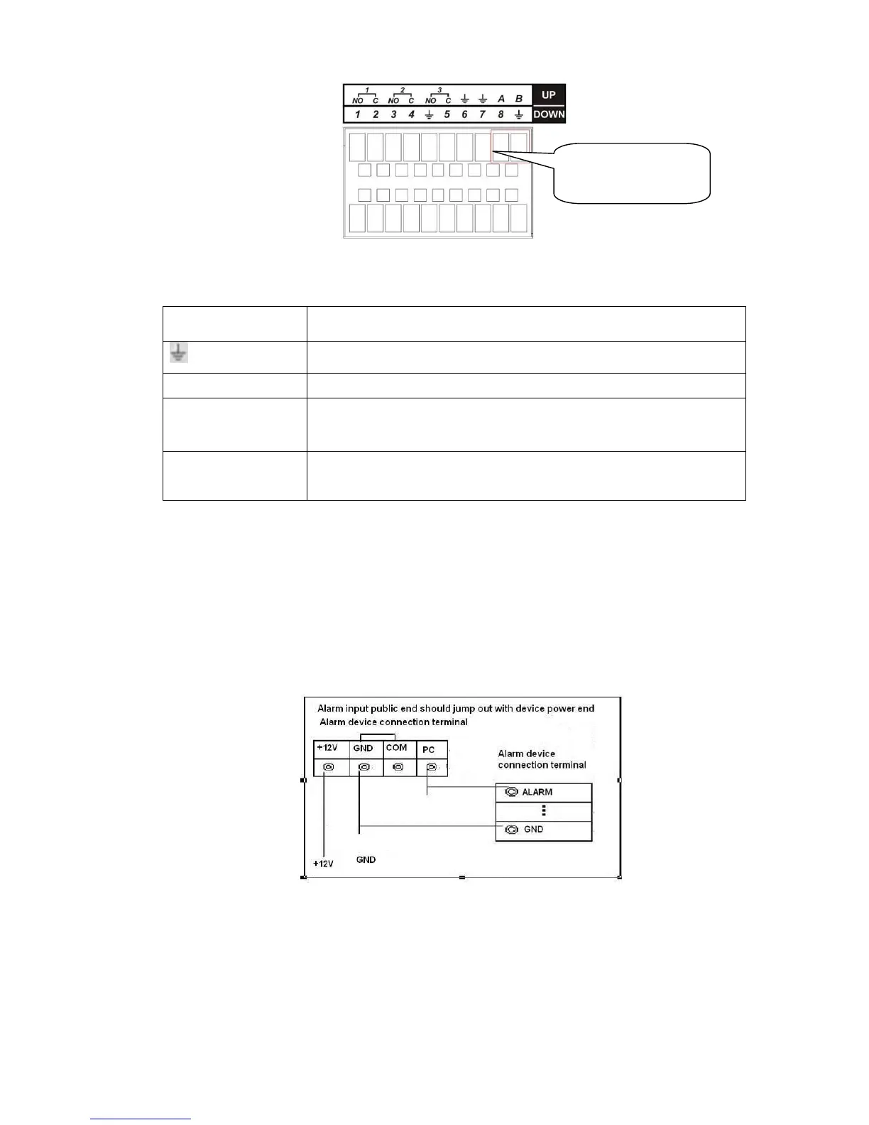
Normal open or Normal close type
Please parallel connect COM end and GND end of the alarm detector (Provide external power to
the alarm detector).
Please parallel connect the Ground of the DVR and the ground of the alarm detector.
Please connect the NC port of the alarm sensor to the DVR alarm input(ALARM)
Use the same ground with that of DVR if you use external power to the alarm device.
Figure 3-3
3.7.3 Alarm Output Port
Provide external power to external alarm device.
To avoid overloading, please read the following relay parameters sheet carefully.
RS485 A/B cable is for the A/B cable of the PTZ decoder.