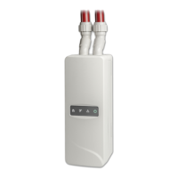
Chapter 2: Installation
26 ModuLaser Modular Aspirating Smoke Detector Installation Manual
Connecting inputs
Connect input devices to the I/P1 and I/P2 connectors.
Inputs are supervised to detect open, activated, and not activated states. Inputs
require a 15 kΩ end-of-line resistor (provided in the accessory kit).
General input activation characteristics are shown in the table below. For power
supply fault supervision activation characteristics, see “Connecting the power
supply fault supervision” on page 27.
Table 5: General input activation characteristics
Activation value (detector) Activation value (display)
15 kΩ ±10% 15 kΩ ±10%
Short circuit (activated)
< 2.7 kΩ < 3.3 kΩ
Open circuit (supervision fault)
> 34.1 kΩ > 470 kΩ
See “Configuring the inputs” on page 56 for input configuration options.
Connecting outputs
Connect output devices to the O/P1, O/P2, and O/P3 connectors.
Outputs are activated by a voltage free relay contact with normally open (NO),
normally closed (NC), and common (C) connections.
See “Configuring the outputs” on page 58 for output configuration options.
Connecting the power supply
Caution: Ensure that the installed power supply covers the power consumption
requirements for your installation. In installations with high power consumption
requirements, additional power supplies may be required.
Connect the power supply to the PSU connector.
The module can be powered by any EN 54-4 or UL/cUL and FM compliant
monitored 24 VDC power supply of sufficient capacity for the installation
requirements.
Note: For compliance with EN 54-20, the module must be powered by a power
supply approved to EN 54-4.
See “Connecting a non-distributed cluster” on page 23, “Connecting a distributed
cluster” on page 24, and “Connecting a hybrid cluster” on page 25 for more
information on power supply requirements for each type of cluster.