Chapter 2: Installation
30 ModuLaser Modular Aspirating Smoke Detector Installation Manual
Addressing modules
Set the unique 7-bit module address using the address DIP switch on the
backplane PCB Figure 6 on page 14). The address range is 1 to 127 for all
modules (including command modules) and is set using the first seven bits of the
DIP switch (bit 8 is not used).
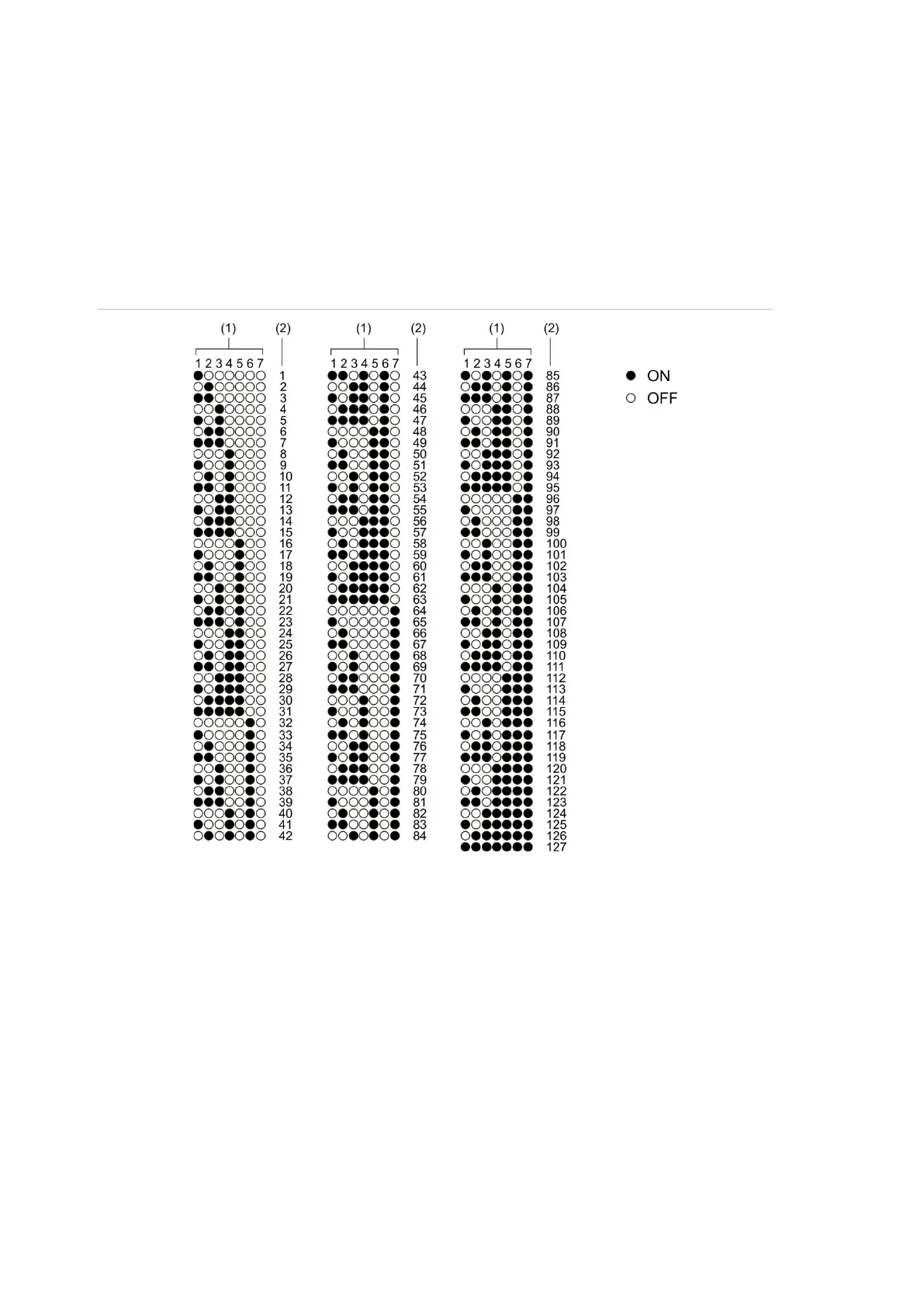
The full range of addresses and their settings is shown in Figure 18 below.
Figure
18
: Address settings
1. DIP switch setting
2. Address