48 Installation and Service Guide
Replacing Parts
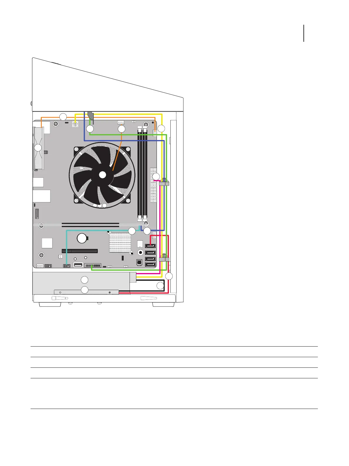
Figure 23: Cable connections inside the E-35A
A Chassis fan C Power supply unit
B CPU fan D HDD
Cable From To
1 Chassis fan cable Chassis fan FRONT FAN connector on motherboard (J30)
2 Fiery QuickTouch USB cable Fiery QuickTouch USB USB 3.0 HDR connector on motherboard (J14)
3 CPU fan cable CPU fan CPU FAN connector on motherboard (J16)
4 Power supply cable Power supply unit a. 4-pin connector on motherboard (J24)
b. 24-pin connector on motherboard(PWRCONN1)
c. HDD SATA power connector