59 Installation and Service Guide
Replacing Parts
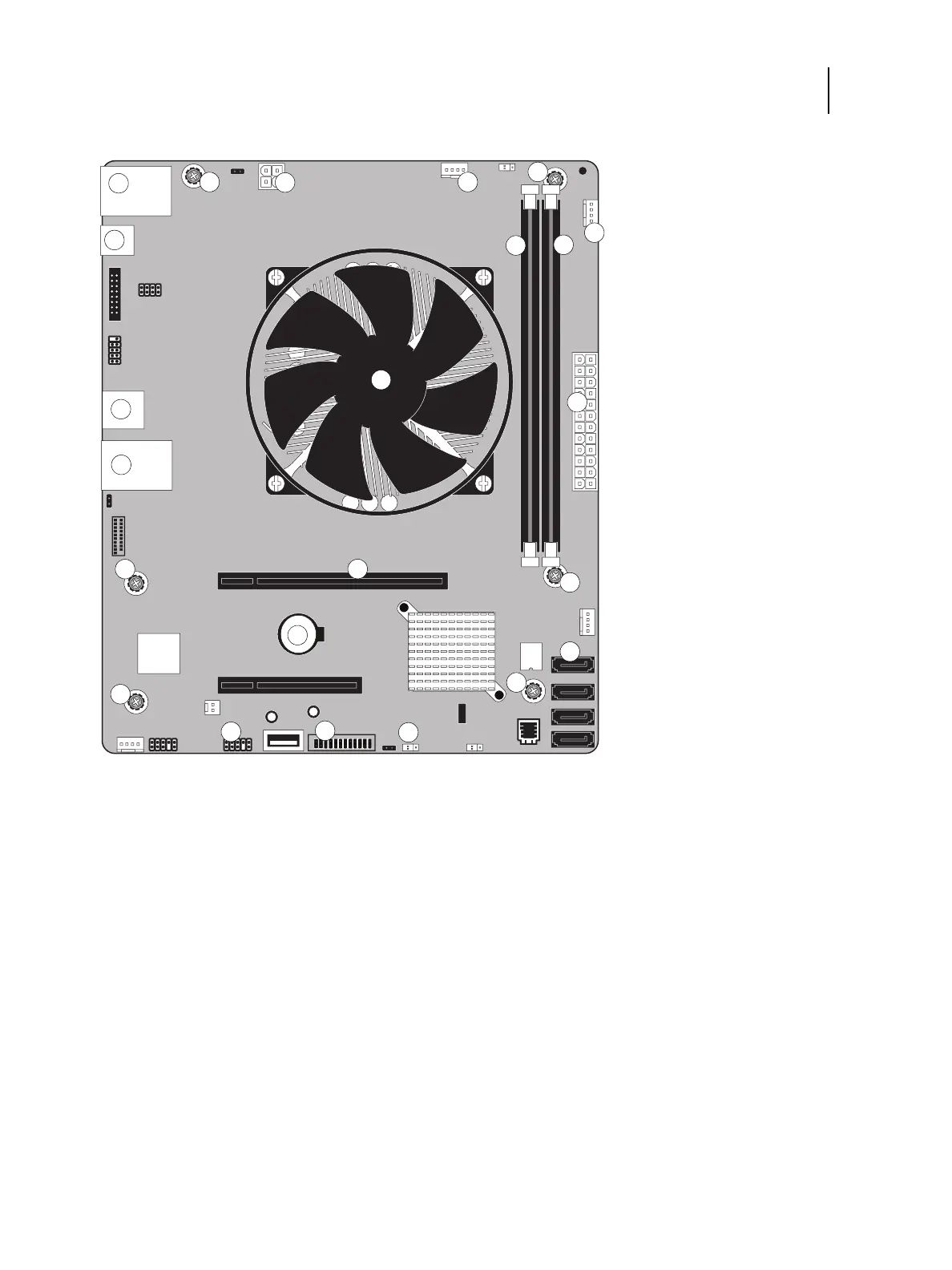
Figure 31: Diagram of the E-35A motherboard
Removing the motherboard
Before you remove the motherboard, you must remove:
• All boards installed on the motherboard
1 Type A USB2.0 ports (x2) / Network cable
port (Upper RJ-45)
7 FRONT FAN connector (J30) 13 Battery (CR1)
2 4-pin power connector (PWRCONN1) 8 Type A USB2.0 connector (x2) 14 HDD data connector (SATA0)
3 CPU FAN connector (J16) 9 CPU and cooling assembly 15 FP HDR power button pins (J11)
4 Display port (J7) 10 24-pin power connector (J24) 16 USB 3.0 HDR connector (J14)
5 DIMM-A0 11 Type A USB3.0 ports (x2) /
Printer
interface (Crossover Ethernet)
port
(Lower RJ-45)
17 Clear CMOS jumper (J17)
6 DIMM-B0 12 Printer interface board (PCIE x16 slot) MS Mounting screws
Note: Any connectors not listed are not used.
MS
MS
10
MS
MS
MS
5
8
MS
6
16
2
3
1
4
7
9
11
12
14
15
17
13