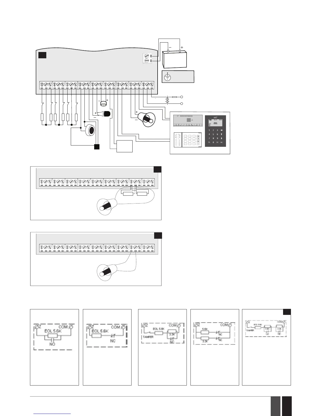
18.3. Wiring Diagrams
18.3.1. General Wiring
C O M
BELL-
BELL+
G
Y
C2
AUX-
AUX+
AC /DC
AC /DC
Z1
C O M
Z2
Z3
C O M
Z4
DATA
+5V
MIC -
MIC +
BUZ-
C1
BUZ+
C O M
C O M
Z6
Z5
MIC
BUZ
SIREN/BELL
iButton®
key reader
Temperature sensor
EKB2EKB3
EPGM1
Z1
Z2
Backup Battery
12V 1.3-7Ah
Metal cabinet
PE terminal
Relay
module
1A max.
Z4
Z3
Z5
Z6
Fuse 500 mA
~230V 50/60HZ
~16-24V
AKU+
AKU-
5,6 kΩ
5,6 kΩ
5,6 kΩ
5,6 kΩ
5,6 kΩ
5,6 kΩ
1 2 3
4 5 6
7 8 9
*
0 #
25
RED +
BLACK -
BELL-
BELL+
SIREN/BELL
1A max.
3,3kΩ 3,3kΩ
26
Siren status monitoring
By default, the system monitors siren status and indicates sys-
tem fault on the keypad if the siren is broken/disconnected.
However, this feature requires a pair of 3,3kΩ nominal resistors
connected in parallel across BELL+ and BELL- terminals.
27
No siren status monitoring
If the siren status monitoring feature is not required, do not
connect any resistor in parallel and disable siren fault indication
on the keypad (see 13. INDICATION OF SYSTEM FAULTS).
18.3.2. Zone Connection Types
Type 1 Type 2 Type 3 Type 4 Type 5
Normally open contact
with 5,6KΩ end of line
resistor
Normally closed con-
tact with 5,6KΩ end of
line resistor
Tamper and 5,6KΩ
end of line resistor
and 3,3KΩ end of line
resistor with normally
closed contact
ATZ Mode: 5,6KΩ end
of line resistor and nor-
mally closed contact
with 3,3KΩ end of line
resistor and normally
closed contact
ATZ Mode: Tamper,
5,6KΩ end of line re-
sistor, 5,6KΩ end of
line resistor with nor-
mally closed contact
and 3,3KΩ end of line
resistor with normally
closed contact.
28