9.4 Phases of the diagnostics test
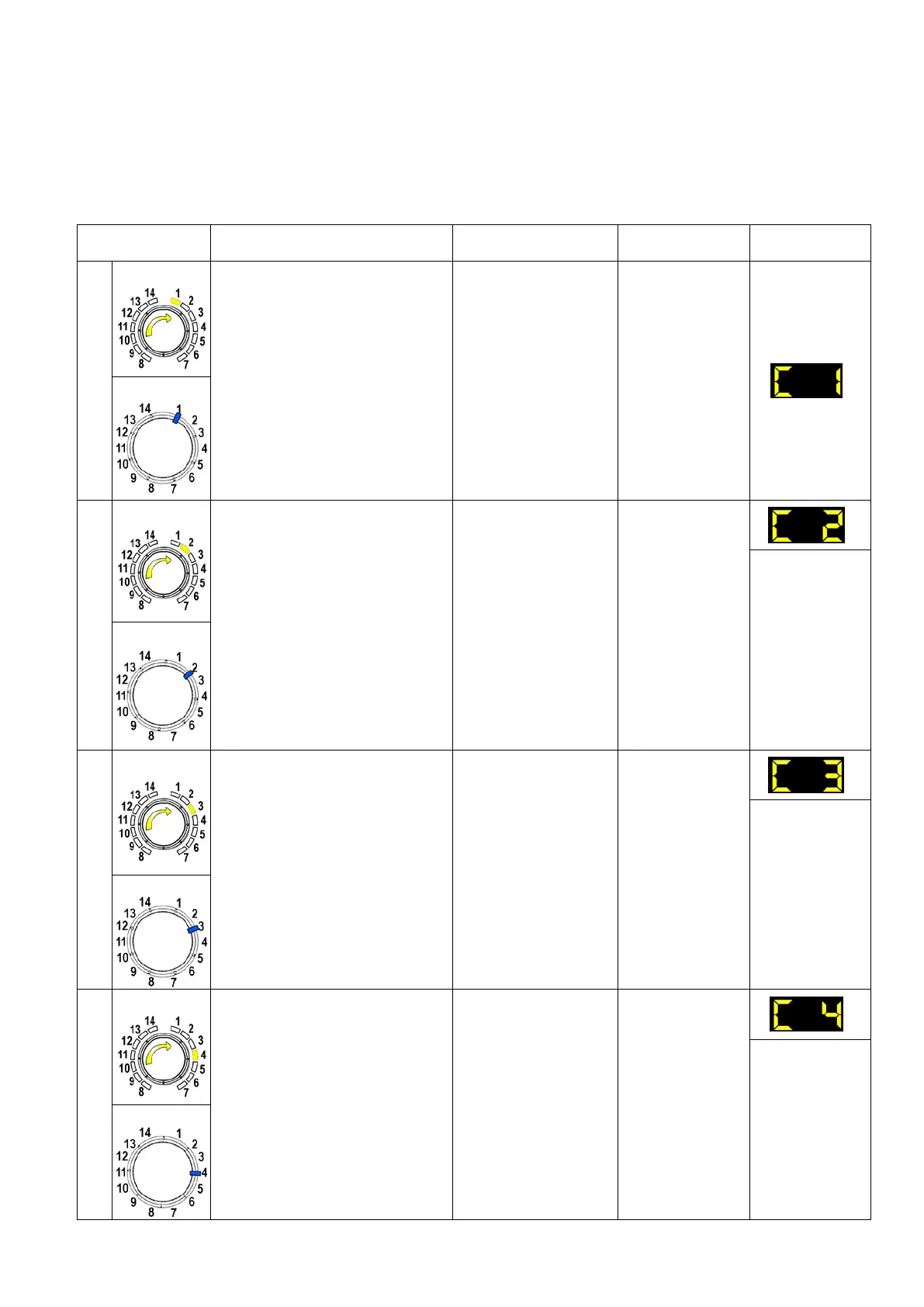
Irrespective of the type of PCB and the configuration of the programme selector, after entering the diagnostic
mode, turn the programme selector dial clockwise to perform the diagnostic cycle for the operation of the various
components and to read any alarms.
Concurrently, a selector control code is shown on the LCD display, which indicates for two seconds the
description in the last column of the table below.
(all alarms are enabled in the diagnostic cycle).
Components activated Working conditions Function tested LCD display
1
- The LEDs, groups of symbols
in the LCD screen and the
backlight of the display are
turned on in sequence
- Touch a sensor to turn on the
group of icons in the LCD
screen or the corresponding
LED and the buzzer sounds at
the same time
Always active
User interface
functioning
TC 4
2
TC 3-2
- Door safety interlock
- Wash solenoid valve
Door closed
Water level below
anti-flooding level
Maximum time 5 min.
Water fill to wash
compartment
Water level in
the tub (mm)
TC 4
3
TC 3-2
- Door safety interlock
- Pre-wash solenoid valve
Door closed
Water level below
anti-flooding level
Maximum time 5 min.
Water fill to
pre-wash
compartment
Water level in
the tub (mm)
4
- Door safety interlock
- Solenoid valve
pre-wash and wash
Door closed
Water level below
anti-flooding level
Maximum time 5 min.
Water fill to
conditioner
compartment
Water level in
the tub (mm)
Technical Support - DMM 35/124 599 75 58-67 Rev.04