1-20
1-201-20
1-20
TOTO
TOTO
TO
CHARGINGCHARGING
CHARGINGCHARGING
CHARGING
CYLINDERCYLINDER
CYLINDERCYLINDER
CYLINDER
TOTO
TOTO
TO
RECOVERYRECOVERY
RECOVERYRECOVERY
RECOVERY
SYSTEMSYSTEM
SYSTEMSYSTEM
SYSTEM
AA
AA
A
BB
BB
B
CC
CC
C
ACCESS VACCESS V
ACCESS VACCESS V
ACCESS V
ALAL
ALAL
AL
VEVE
VEVE
VE
TOTO
TOTO
TO
CHARGINGCHARGING
CHARGINGCHARGING
CHARGING
CYLINDERCYLINDER
CYLINDERCYLINDER
CYLINDER
AA
AA
A
CC
CC
C
BB
BB
B
ACCESS VACCESS V
ACCESS VACCESS V
ACCESS V
ALAL
ALAL
AL
VEVE
VEVE
VE
TOTO
TOTO
TO
RECOVERYRECOVERY
RECOVERYRECOVERY
RECOVERY
SYSTEMSYSTEM
SYSTEMSYSTEM
SYSTEM
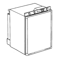
Step 3.Step 3.
Step 3.Step 3.
Step 3. Leave valve A closed and valve C open. System compressor still running,
open valve B to allow refrigerant to flow into the recovery system. After vacuum
has been held, turn off system compressor.
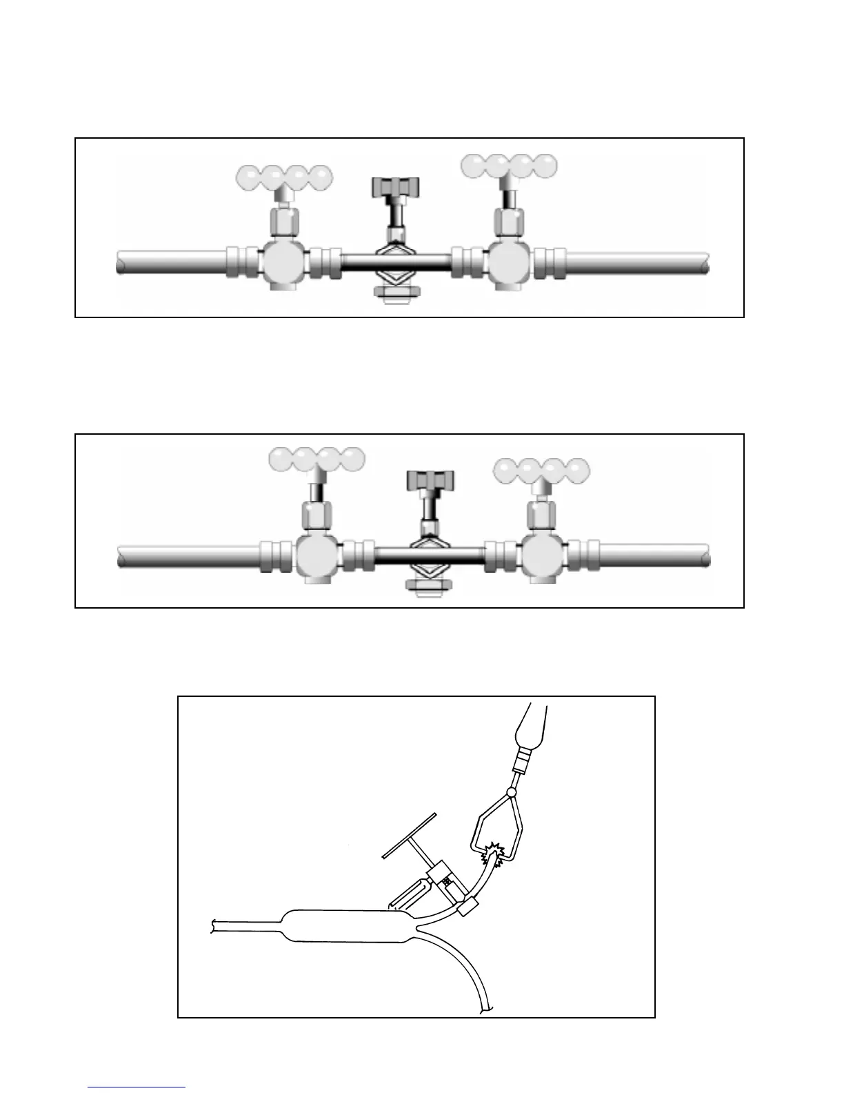
Step 4.Step 4.
Step 4.Step 4.
Step 4. Close valve B. Liquid refrigerant still present to valve A and charging cylinder
pressure is 30 p.s.i.g. above room ambient. Open valve A to slowly allow the proper
refrigerant charge into the system. Close valve A. If needed, valve C can be closed
and valves A and B opened to recover refrigerant in the hoses and charging cylinder.
Step 5.Step 5.
Step 5.Step 5.
Step 5. Use pinch-off tool to seal the process tube between the drier and the access
valve. Remove the access valve and braze the opening. After the required five minute
equalization time, start the system compressor.