2-4
22. Test for leaks.
23. Install the machine compartment cover.
24. Test run the refrigerator to make sure
it is operating properly.
ELECTRICAL SYSTEM
The wiring diagram is located in the con-
trol housing area.
All electrical components are grounded
to the cabinet.
The green/yellow center conductor in
the power cord is attached to the cabi-
net to provide a ground circuit when the
cord is plugged into a properly
grounded outlet.
After replacing an electrical component,
always reconnect the ground wire.
The electrical outlet should be checked
to make sure it is properly wired.
Check the outlet with a circuit tester.
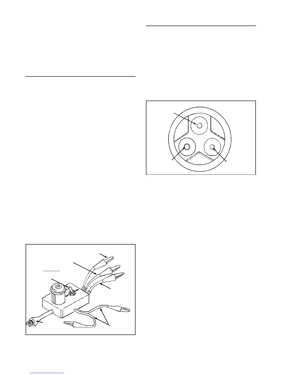
Capacitor
Start
Run
Common
SWITCH:
Off, Run, Start
Power
Plug
Testing the Compressor Direct
Testing the compressor with no other wir-
ing in the circuit is called the direct test
method. Remove all electrical components
from the compressor in order to perform
this test. It is recommended that a com-
pressor tester as illustrated be used to
make this test.
Start
Run
Common
The tester leads are marked RUN, START,
and COMMON. Connect the common lead
to the common terminal of the compres-
sor, the start lead to the start terminal and
the run lead to the run terminal. The com-
pressor terminal arrangements are illus-
trated above. The other two leads are for a
start capacitor (if used). When not in use,
attach the two leads together and place the
toggle switch in the OFF position. There
should not be any bare leads touching the
cabinet. Plug in the tester and flip the switch
to the start position. When the compres-
sor starts, release the switch to the run po-
sition. If the compressor is operative, it will
continue operating on the run windings. If
the compressor fails to run, the compres-
sor is defective and must be replaced.
COMPRESSOR TESTER