1-19
1-191-19
1-19
SWEEP AND FINAL CHARGESWEEP AND FINAL CHARGE
SWEEP AND FINAL CHARGESWEEP AND FINAL CHARGE
SWEEP AND FINAL CHARGE
TOTO
TOTO
TO
CHARGINGCHARGING
CHARGINGCHARGING
CHARGING
CYLINDERCYLINDER
CYLINDERCYLINDER
CYLINDER
TOTO
TOTO
TO
RECOVERYRECOVERY
RECOVERYRECOVERY
RECOVERY
SYSTEMSYSTEM
SYSTEMSYSTEM
SYSTEM
BB
BB
B
CC
CC
C
ACCESS VACCESS V
ACCESS VACCESS V
ACCESS V
ALAL
ALAL
AL
VEVE
VEVE
VE
AA
AA
A
The sweep charge is a method of purging
the sealed system of moisture, air and po-
tential contaminants. Also during this pro-
cedure, the system may be checked for
leaks before the final charge. If this proce-
dure is followed as outlined, it will allow for
the capture of 90-95 percent of the available
refrigerant, thereby ensuring that the sys-
tem will operate as designed.
The sweep procedure for R134a refrigerant
systems is made after the system has been
repaired and/or flushed. Three (3) ounces
of refrigerant R134a is added to the system,
circulated by the compressor for 5 minutes
and recovered. Since a new drier - part
#13900-1 #13900-1
#13900-1 #13900-1
#13900-1 has already been installed, a high
side process tube is available. Install a tem-
porary access valve to this process tube
close enough to the end of the tube so that
the tube can be pinched closed behind the
valve and the opening sealed shut after the
valve is removed. Remember, no access
valve is to be left on the sealed system. Con-
nect a 1/4 inch flare tee to the access valve.
Connect a quick coupler hand valve to each
side of the tee. To one hand valve, connect
the hose from the charging cylinder. To the
other valve, connect the hose to the recov-
ery system.
The following steps take you through the
sweep and final charge.
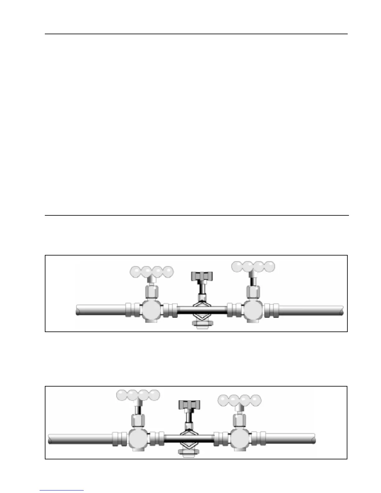
Step 2Step 2
Step 2Step 2
Step 2. With liquid refrigerant present to valve A, valve B closed and valve C open
(C will remain open throughout sweep procedure), open valve A to allow three (3)
ounces of refrigerant into the system. Close valve A. Check low side for leaks. After
system has equalized (about 3 to 5 minutes), start system compressor, check for high
side leaks and allow refrigerant to circulate in the system about 5 minutes.
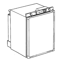
Step 1.Step 1.
Step 1.Step 1.
Step 1. Set up of valves: temporary access valve (C) piercing drier process tube,
connected to flare tee, hand valve (A) to charging cylinder, hand valve (B) to recovery
system.
BB
BB
B
AA
AA
A
CC
CC
C
ACCESS VACCESS V
ACCESS VACCESS V
ACCESS V
ALAL
ALAL
AL
VEVE
VEVE
VE
TOTO
TOTO
TO
RECOVERYRECOVERY
RECOVERYRECOVERY
RECOVERY
SYSTEMSYSTEM
SYSTEMSYSTEM
SYSTEM
TOTO
TOTO
TO
CHARGINGCHARGING
CHARGINGCHARGING
CHARGING
CYLINDERCYLINDER
CYLINDERCYLINDER
CYLINDER