2-14
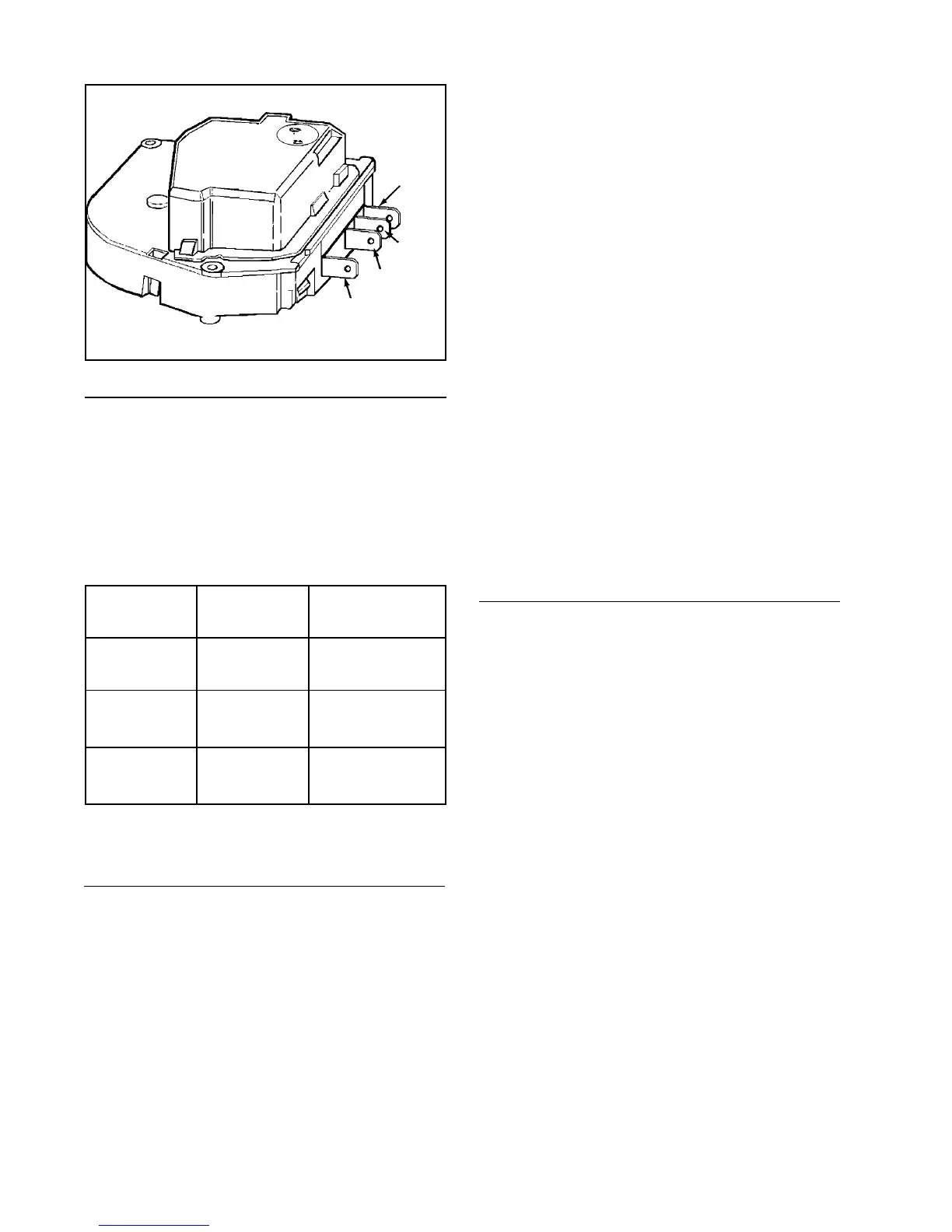
Checking the Defrost Timer
Disconnect all wires from the timer and at-
tach ohmmeter probes to the terminals
specified in the accompanying chart. If no
continuity is indicated, the timer is defec-
tive.
To Test Turn Timer Check Between
Knob To Terminals
Timer Motor Leave as is 1 & 3 *
Circuit
Defrost 1st Click 1 & 2
Circuit
Compressor 2nd Click 1 & 4
Circuit
#1
White
#3 Blue
#4 Orange
4. Remove the fascia/radiant shield
mounting screws. Remove the control
housing mounting screw at the back of
the control housing. Slide the control
housing to the right and lower it from
the control housing supports.
5. Disconnect the temperature control
housing electrical quick disconnects.
6. Remove the temperature control hous-
ing from the refrigerator and place on a
flat work surface.
7. Remove the two timer mounting
screws.
8. Disconnect the electrical connector
from the timer.
9. Install the replacement timer in reverse
order of removal.
ADAPTIVE DEFROST CONTROL
The adaptive defrost control assembly is a
microprocesser controlled defrost timer.
This new control allows defrost to occur
only when needed, compared to mechani-
cal timers which defrost at a preset interval
whether it is necessary or not. The new
control will continually adjust defrost inter-
vals based on the amount of time the de-
frost heater is energized. This allows the
defrost intervals to be adjusted closer to
the optimum defrost interval based on use,
thus saving energy.
#2 Yellow
*See Maytag Monthly Bulletin, June 1993 volume:03 Issue 40
Page 1 Low watt Timers (This test works on all low watt timers.)
Timer Replacement
1. Disconnect the unit from the power
source.
2. Open the fresh food door and remove
any items on the top shelf.
3. Remove the light shield cover by pull-
ing down on the back corners of the
cover and sliding the cover forward.