4-2
4-24-2
4-2
Shut-off armShut-off arm
Shut-off armShut-off arm
Shut-off arm
Screw adjustmentScrew adjustment
Screw adjustmentScrew adjustment
Screw adjustment
Mold attachment Mold attachment
Mold attachment Mold attachment
Mold attachment
(Screw access ports) (Screw access ports)
(Screw access ports) (Screw access ports)
(Screw access ports)
Module, MotorModule, Motor
Module, MotorModule, Motor
Module, Motor
, and Support Assembly:, and Support Assembly:
, and Support Assembly:, and Support Assembly:
, and Support Assembly:
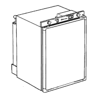
Insert Phillips screwdriver in access ports
of module. Loosen both screws. Discon-
nect shut-off arm. Pull mold from support
assembly. To remove module only, remove
3 Phillips screws and pull module out of
housing.
NOTE:NOTE:
NOTE:NOTE:
NOTE:
Do not short any contacts otherDo not short any contacts other
Do not short any contacts otherDo not short any contacts other
Do not short any contacts other
than those specified. Damage to the icethan those specified. Damage to the ice
than those specified. Damage to the icethan those specified. Damage to the ice
than those specified. Damage to the ice
maker can result.maker can result.
maker can result.maker can result.
maker can result.
Ice Maker Unplugged:Ice Maker Unplugged:
Ice Maker Unplugged:Ice Maker Unplugged:
Ice Maker Unplugged:
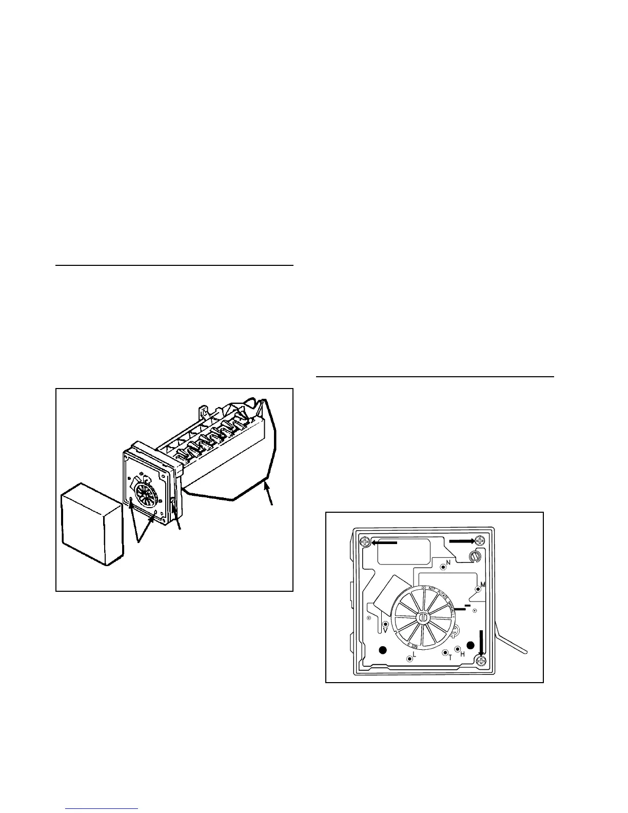
Test points L&H will check the resistance
of the heater (72 ohms). Replace the
mold and heater assembly if not near
this value (+/- 10 ohms).
(Ejector blades should be at the end of
the cycle position.)
SERVICE PROCEDURESSERVICE PROCEDURES
SERVICE PROCEDURESSERVICE PROCEDURES
SERVICE PROCEDURES
Cover:Cover:
Cover:Cover:
Cover: Pull water adjustment knob first and
snap off cover. Index knob and reinstall in
same position for same water fill. (Some
units may not have index knobs.)
Shut-Shut-
Shut-Shut-
Shut-
Off Arm: Off Arm:
Off Arm: Off Arm:
Off Arm: Pull out from white bush-
ing. Reinsert to full depth. See page 5-15
for detailed position.
Mold & Heater: Mold & Heater:
Mold & Heater: Mold & Heater:
Mold & Heater: Remove module and sup-
port assembly. Install on new mold and
heater assembly.
Bimetal: Bimetal:
Bimetal: Bimetal:
Bimetal: Remove module and support as-
sembly. Pull out retaining ring clips with
bimetal.
Fill Cup: Fill Cup:
Fill Cup: Fill Cup:
Fill Cup: Remove module and support as-
sembly. Remove ejector blades and shut-
off arm. Pull fill cup up from mold.
Ejector Blades or Stripper: Ejector Blades or Stripper:
Ejector Blades or Stripper: Ejector Blades or Stripper:
Ejector Blades or Stripper: Remove mod-
ule and support assembly. When reinstall-
ing ejector blades, realign "D" coupling with
module cam.
ACCESSING THE CONTROL BOACCESSING THE CONTROL BO
ACCESSING THE CONTROL BOACCESSING THE CONTROL BO
ACCESSING THE CONTROL BO
XX
XX
X
To remove motor and contact assembly
from control box, take out three screws
(see arrows) and pull free
after disconnect-after disconnect-
after disconnect-after disconnect-
after disconnect-
ing the shut-off arm.ing the shut-off arm.
ing the shut-off arm.ing the shut-off arm.
ing the shut-off arm.