3-8
3. During activation, check for approxi-
mately 100 volts AC from PIN 7 to PIN2.
If 100 volts AC is not present, replace
the board. If voltage is present, check
the solenoid and associated wiring.
IF THE DOOR FAILS TO CLOSE:
1. Disconnect the unit from the power
source if the door still stays open.
Check the solenoid, door hinge and
spring assembly. If the door closes, go
to step 2.
2. Plug the unit in, check for 0 volts AC
from PIN 1 to PIN 4. If you read 115
volts AC check switches and wiring. If
voltage reads 0, go to step 3.
3. Disconnect the unit from the power
source and remove the circuit board.
Check continuity from PIN 7 to PIN 2.
If shorted, replace the circuit board.
Fountain Door Delay
Normal door delay will be approximately 2
seconds.
Excessive Door Delay
Check for mechnical obstruction, if none
replace PC board.
Short Door Delay
1. Check for 115 volts AC between PIN 3
and PIN 1. This ensures proper wiring
and good connection. Low voltage
may represent a problem in wiring con-
nections or at outlet.
2. Check for 115 AC between PIN 1 and
Pin 4 when dispenser switch is
engaged.
The following checks should only be made
by a Qualified Service Technician.
1. Disconnect unit from the power
source.
2. For easy access of the PC board, per-
form steps 1 through 5 of Ice and Wa-
ter Fountain Bracket Removal.
3. Make sure everything is clear. Apply
power to the refrigerator and perform
the following checks with a volt
ohmmeter.
IF DOOR FAILS TO OPEN:
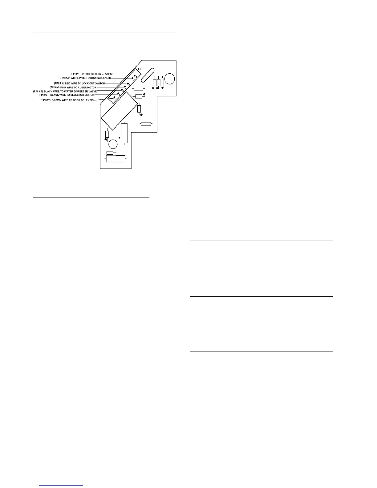
Note: The following checks will be at
terminal board connector T1.
1. Check for 115 volts AC from PIN 3 to
PIN 1. (Lock out switch must be
closed.)
2. Check for 115 volts AC from PIN 4 to
PIN 1 when selector is set to crushed
or cubed and actuator is depressed.
If not there, check selector switches,
actuator switch and associated wiring.
PC BOARD CHECKS