2-16
3. Disconnect the timer wire harness con-
nector from the defrost timer.
4. Set the ohmmeter to R x 1K scale and
connect the probes to the No. 2 and
No. 3 terminals of the disconnect plug.
5. The meter should read between 20 to
40 ohms. The resistance is not critical.
If there is continuity between terminals
No. 2 and 3, the defrost heater is in op-
erative condition. If there are no resis-
tance readings (open circuit) the defrost
heater and thermostat must be checked
individually.
NOTE: When using the meter, avoid
touching the probes as this could result
in a false reading and misdiagnosis.
To test the defrost heater and thermostat
when the evaporator temperature is +15ºF.
or below, proceed as follows:
1. Disconnect the unit from the power
source and plug it into a watt meter.
2. Plug the watt meter into power source
and manually advance the defrost timer
to the defrost cycle. See the defrost
timer section for information on manu-
ally advancing the timer.
3. The watt meter should read between
345 and 475 watts depending on the
model (total wattage of the timer mo-
tor and defrost heater). Should the
reading be 0 to 4.5 watts, the defrost
heater or thermostat is defective. To
further isolate the defective part, pro-
ceed to step 4.
4. Disconnect the unit from the watt meter.
5. Follow steps 2 and 3 of testing the
heater and thermostat when the evapo-
rator temperature is +15ºF. or higher.
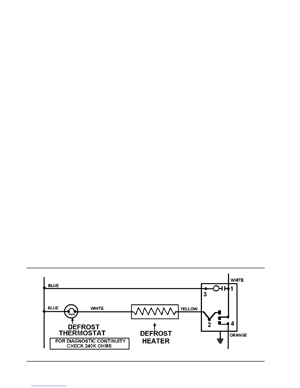
6. If the meter reads approximately 240K
ohms, the defrost thermostat is defec-
tive.
To use an ohmmeter, set the meter to R x
1K scale. If the reading is approximately 20
to 40 ohms, the defrost heater and thermo-
stat are operative.