8
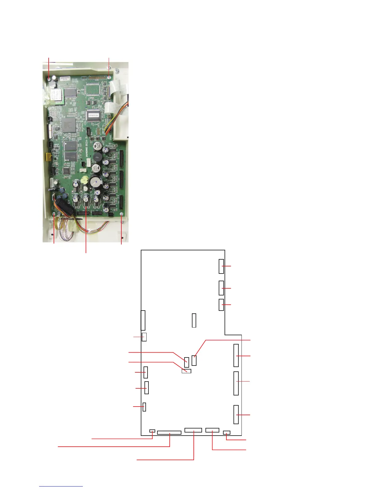
Driving motor
Phase sensor
Board A schematic
Printed circuit board U1 relay (24-pin)
Printed circuit board U2 relay (18-pin)
Printed circuit board U2 relay (20-pin)
Knee lifter sensor
LCD
Printed circuit board U1 relay (26-pin)
Printed circuit board B (USB board)
Foot control
Replacing Electronic Components
Printed circuit board A
NOTE:
Do not disconnect the connectors by pulling on cord.
To disconnect the connectors, grasp the connector, not the
cord.
To remove:
1. Remove the front cover (see page 5).
2. Disconnect the connectors. Remove the setscrews
(4 pcs.) and printed circuit board A.
To attach:
Follow the above procedure in reverse.
After replacing the printed circuit board A, adjust the following
parts:
• Knee Lifter (see page 48)
• Cloth guide start position (see page 53)
• Remaining bobbin thread sensor (see page 49)
• Presser bar height (see page 44)
• Embroidery foot height (see page 45)
* Adjust the embroidery foot height after the presser bar
height adjustment.
Printed circuit board A
Setscrew
Printed circuit board K1 relay (6-pin)
Printed circuit board K1 relay (26-pin)
Printed circuit board K1 relay (30-pin)
Printed circuit board U2 relay (14-pin)
TTP (Touch panel)
LCD module
Switching power supply unit
Auxiliary power supply unit
Setscrew
Setscrew
Setscrew