62
Mechanical Adjustment
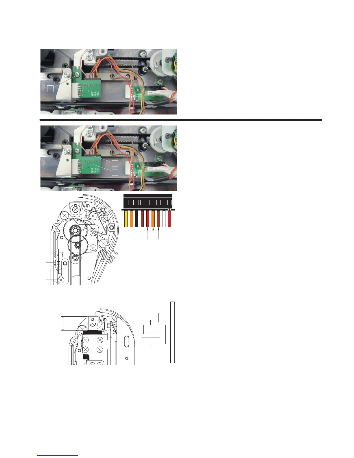
Replacing Printed Circuit Board S2
z Remove the Y-carriage cover (lower) (refer to pages 51-
52).
Remove the setscrew
q.
Disconnect the connector and flexible cable from the
printed circuit board S2.
Remove the printed circuit board S2.
q
ReplacingY-sensor
•RemovingY-sensor
z
Remove the Y-carriage cover (lower) (refer to pages 51-
52).
Disconnect the connector
q from the printed circuit board
S2
w.
x Pry up the lock tab of the connector with a precision driver
and pull out the red
e, orange r and brown t.
c Remove the setscrew y.
Remove the Y-sensor.
q
w
ert
y
•AttachingY-sensor
z
Adjust the Y-sensor height so the shielding plate u should
be positioned at the middle of the sensor
i as illustrated.
Tighten the setscrew
y to attach the Y-sensor.
Insert the cords
e, r and t to the connector.
Plug the connector to the printed circuit board S2.
x Attach the embroidery unit to the MC12000.
Insert the machine plug into the power inlet.
Insert the power supply plug into the wall outlet and turn
the power switch on.
c The embroidery unit carriage position is initialized.
The range A (between the edge of Y-carriage LM guide
and the edge of carriage) should be 13.5 mm.
If not, turn the setscrew
o and adjust the Y-sensor
position.
If the range A is larger than 13.5 mm, move the Y-sensor
set plate in the direction of “B”.
If the range A is smaller than 13,5 mm, move the Y-sensor
set plate in the direction of “C”
Initialize the embroidery unit again and be sure the range
between A and B is in the range of 10.1 mm to 11.1 mm. If
not, repeat the procedure and adjust the range again.
13.5 mm
i
u
o
A
C
B