124
EMC Connectrix B Series v6.2 ED-DCX-4S-B Hardware Reference Manual
Removal and Replacement Procedures (RRPs)
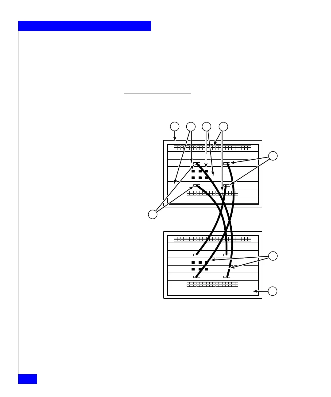
Figure 29 and Figure 30 on page 125 show two of the acceptable cabling
configurations for the ICL feature between two ED-DCX-4S-B chassis
and between an ED-DCX-4SB and an ED-DCX-B. The drawings show the
cables attached between the blades in slot 3 on one chassis and slot 6 on
the second chassis. It is also acceptable to attach the cables from slot 3 on
one chassis to slot 3 on the second chassis (or slot 6 to slot 6) as long as
the left-to-right (top-to-bottom) rule is followed.
4. Once all the cables are attached, see the EMC Connectrix B Series
Fabric OS Administrator’s Guide for the configuration procedure.
Figure 29 ICL cable connections – between two ED-DCX-4S-B chassis
1 Chassis 1 5 ICL connector (ICL 1)
2 Core switch blades (CR4S-8) 6 ICL connector (ICL 0)
3 Control processor blades (CP8) 7 ICL cables
4 Port blades 8 Chassis 2
 Loading...