58 Configure Frequency/Digital output sources
Section 5: Calibrate and configure the meter 3410 Series Gas Ultrasonic Meters Operations Manual
January 2018 3-9000-777 Rev E
• TTL (internally powered by the meter 0-5 VDC signal)
Channel B Phase options:
• Lag forward, Lead reverse (Phase B lags Phase A while reporting forward flow, leads Phase
A while reporting reverse flow)
• Lead forward, Lag reverse (Phase B leads Phase A while reporting forward flow, lags Phase
A while reporting reverse flow)
Phase A and Phase B output (based on flow direction)
• Reverse flow - output only reports flow in the reverse direction. For frequency outputs,
Phase B of the output is 90 degrees out of phase with Phase A.
• Forward flow - output only reports flow in the forward direction. For frequency outputs,
Phase B of the output is 90 degrees out of phase with Phase A.
• Absolute - output reports flow in both directions. For frequency outputs, Phase B of the
output is 90 degrees out of phase with Phase A.
• Bidirectional - output reports flow on Phase A only in the forward direction and on Phase B
only in the reverse direction.
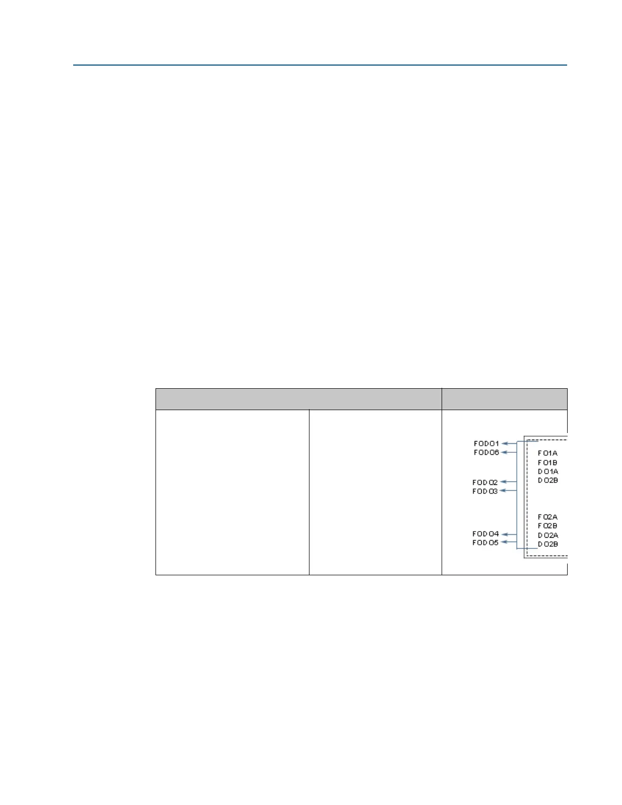
The outputs for FODO1 and Digital Output1 (Group 1 on the CPU Module) share a common
ground and have 50V isolation. FODO2 and FODO3 (Group 2 on the CPU Module) share a
common ground and have 50V isolation. This allows an output to be connected to a different
flow computer. The outputs are opto-isolated from the CPU Module and have a withstand
voltage of at least 500V rms dielectric.
Table 5-6 Frequency/Digital Outputs possible configurations
Frequency/Digital output Source configuration
Frequency /Digital Output 1
a
Frequency /Digital Output 2
b
Frequency /Digital Output 3
Frequency /Digital Output 4
Frequency /Digital Output 5
b
Frequency /Digital Output 6
b
a. Solid blue line denotes valid selection for Frequency/Digital Output 1.
b. Black dashed -line denotes valid selections for Frequency/Digital Output 2 and Frequency/Digital
Output 3.
• Frequency output 1A
• Frequency output 1B
• Digital output 1A
• Digital output 1B
• Frequency output 2A
• Frequency output 2B
• Digital output 2A
• Digital output 2B

 Loading...


