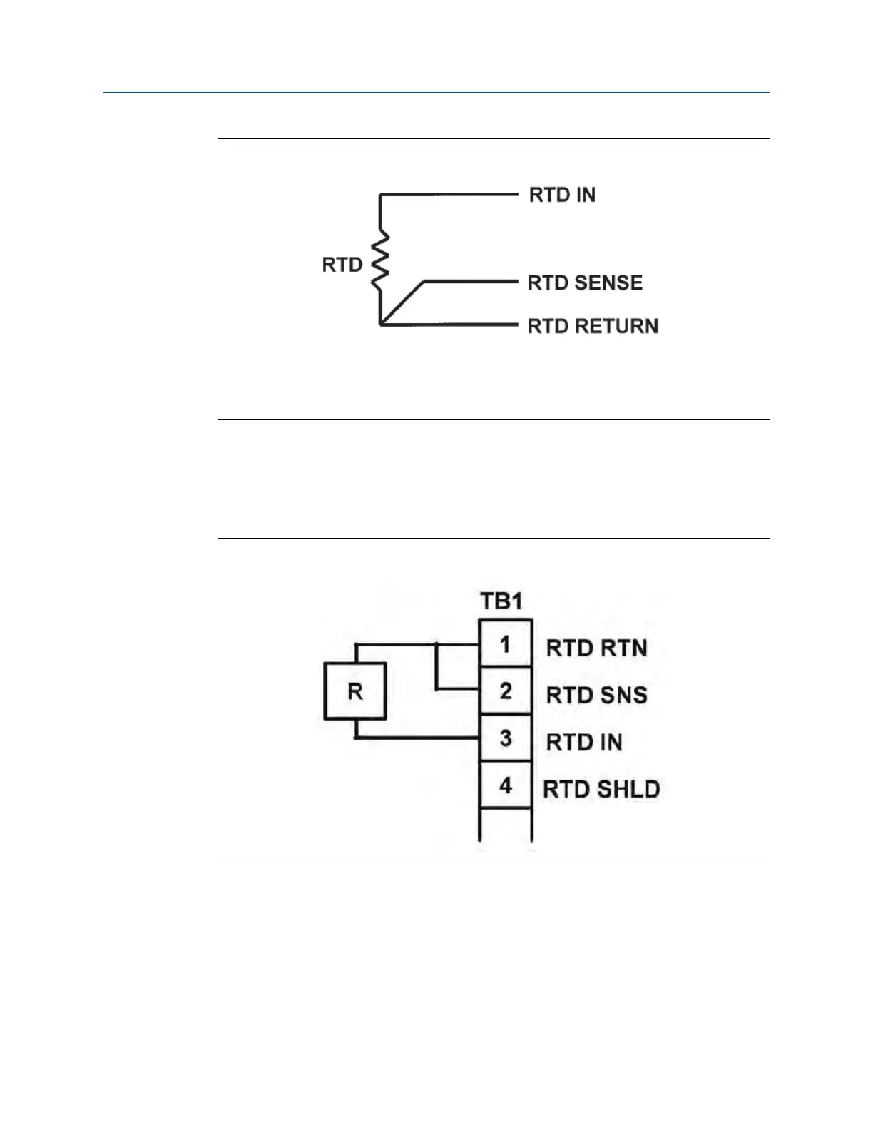
Three-Wire RTD ConfigurationFigure 11-3:
Although only two wires are required to connect the RTD to the transmitter, using a third (and sometimes
fourth) wire allows the transmitter to correct for the resistance of the lead wires and for changes in the
lead wire resistance with temperature.
11.7.2 Simulating temperature
To simulate the temperature input, wire a decade box to the transmitter or junction box as
shown in Figure 11-4.
Simulating RTD InputsFigure 11-4:
To check the accuracy of the temperature measurement, set the resistor simulating the
RTD to the values indicated in the table and note the temperature readings. The measured
temperature might not agree with the value in the table. During sensor calibration, an
offset might have been applied to make the measured temperature agree with a standard
thermometer. The offset is also applied to the simulated resistance. The transmitter is
measuring temperature correctly if the difference between measured temperatures
equals the difference between the values in the table to within ±0.1 °C.
Troubleshooting
96 Rosemount TCL

 Loading...


