6
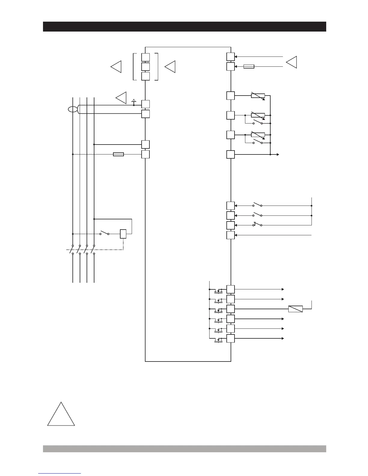
2.3ElectricalConnection
TRANS-MINIAUTO threephaseconnectionsschematic
13
11
12
BATTERY -
BATTERY +
23
22
14
15
BATTERY -
16
FUSE-2
1-
3-
4-Currenttransformerssecondaryshouldbegrounded.
Connecttheunitasshownintheappropriatediagram.Besuretoconnectthebattery
supplytherightwayroundandbatterynegativeshouldbegrounded.
2- TheCANinterfacerequiresthata120Ohmsterminatorisfittedtoeachendofthe
communicationslink. Thisterminationresistorisfittedinternallyintotheunit.Soitisnot
requiredexternally. ThescreenisgroundedatoneendONLY.
ScreenedcablemustbeusedforconnectingtheMagneticPickup,ensuringthatthe
screenisgroundedatoneendONLY.
3
1
21
-
+
MPU
EmergencyStopor
ConfigurableInput-1
2
1
L1
GENERATOR
L2
L3
N
4
3
Max.300VV
FUSE-1
4
SCR
SCR
L(-)
J1939ECUs
H(+)
2
!
!
!
!
!
G
TO
LOAD
RL1
FUSE
FUSE-2 7A. T
-1 2A. T
D+(W.L.)
Charge Alt.
ConfigurableInput-3
RemoteStartor
ConfigurableInput-2
18
17
20
19
SenderCommon
ToEngine
Earth
*
*
ITCANBEUSED
AS A DIGITAL INPUT
BY SELECTING
FROMTHEPROGRAM
PARAMETERS
*
*
OilPressureSender
orLowOilPressureSwitch
TemperatureSender
orHighTemperatureSwitch
Configurable AnalogInput
ConfigurableOutput-4
7 8
9
10
ConfigurableOutput-3
TRANSISTOROUTPUTS
MAX.1 A
BATTERY +
6
FuelOr
Output-1Configurable
CrankOr
Output-2Configurable
5
ConfigurableOutput-5
ConfigurableOutput-6
BATTERY -
RL1