126 Functional description CG Drives & Automation 01-7491-01r0
Acceleration Time to Minimum
Speed [335]
If minimum speed, [341]>0 rpm, is used in an application,
the AC drive uses separate ramp times below this level. With
“Acc<MinSpeed [335]” and “Dec<MinSpeed [336]” you can
set the required ramp times. Short times can be used to
prevent damage and excessive pump wear due too little
lubrication at lower speeds. Longer times can be used to fill
up a system smoothly and prevent water hammer due to
rapidly exhausting air from the pipe system.
If a Minimum speed is programmed, this parameter will be
used to set the acceleration time parameter [335] for speeds
up to minimum speed at a run command. The ramp time is
defined as the time it takes for the motor to accelerate from
0 rpm to nominal motor speed.
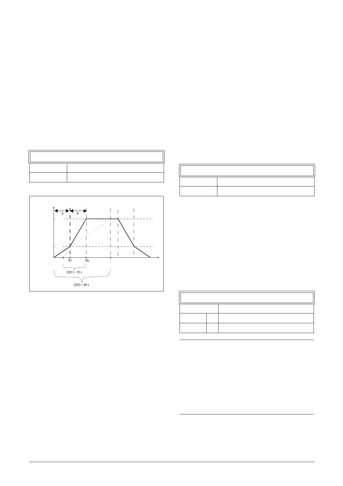
Fig. 104 Calculation example of accelerating times
(graphics not proportional).
Example
“Motor speed [225]” 3000 rpm
Minimum speed [341] 600 rpm
Maximum speed [343] 3000 rpm
Acceleration time [331] 10 seconds
Deceleration time [332] 10 seconds
Acc>Min speed[335] 40 seconds
Dec<Min speed[336] 40 seconds
A. The drive will start from 0 rpm and accelerate to
Minimum speed [341] = 600 rpm in 8 seconds
according to ramp time parameter
Acc>Min speed [335].
Calculated as following:
600 rpm is 20% of 3000 rpm => 20% of 40 s = 8 s.
B. The acceleration continues from minimum speed level
600 rpm to maximum speed level 3000 rpm with
acceleration rate according to ramp time Acceleration
time [331].
Calculate by following:
3000 - 600= 2400 rpm which is 80 % of 3000 rpm =>
acceleration tim is 80 % x 10 s = 8 s.
This means that the total acceleration time from 0 -
3000 rpm will take 8 + 8 = 16 seconds.
Deceleration Time from Minimum
Speed [336]
If a minimum speed is programmed, this parameter will be
used to set the deceleration time from the minimum speed
to 0 rpm at a stop command. The ramp time is defined as
the time it takes for the motor to decelerate from the
nominal motor speed to 0 rpm.
Acceleration Ramp Type [337]
Sets the type of all the acceleration ramps in a parameter set.
See fig. 105. Depending on the acceleration and
deceleration requirements for the application, the shape of
both the ramps can be selected. For applications where speed
changes need to be started and stopped smoothly, such as a
conveyor belt with materials that can drop following a quick
speed change, the ramp shape can be adapted to a S-shape
and prevent speed change shocks. For applications that are
not critical in this, the speed change can be fully linear over
the complete range.
335 Acc<Min Spd
Default: 10.0 s
Range: 0.50-3600 s
time
rpm
Motor Speed
Max speed
Min speed
[341]
[343]
[225]
3000
600
336 Dec<Min Spd
Default: 10.0 s
Range: 0.50-3600 s
337 Acc Rmp
Default: Linear
Linear 0 Linear acceleration ramp.
S-Curve 1 S-shape acceleration ramp.
NOTE: For S-curve ramps the ramp times, [331] and
[332], defines the maximum acceleration and
deceleration rated, i.e. linear part of S-curve, just as
for the linear ramps. The S-curves are implemented
so that for a speed step below sync speed the ramps
are fully S-shaped while for larger steps the middle
part will be linear. Therefore will a S-curve ramp from
0 –sync speed take 2 x Time while a step from 0–2 x
sync speed will take 3 x Time (middle part 0.5sync
speed – 1.5sync speed linear). Also valid for menu
[338], Deceleration ramp type.

 Loading...

