CG Drives & Automation 01-7491-01r0 Functional description 131
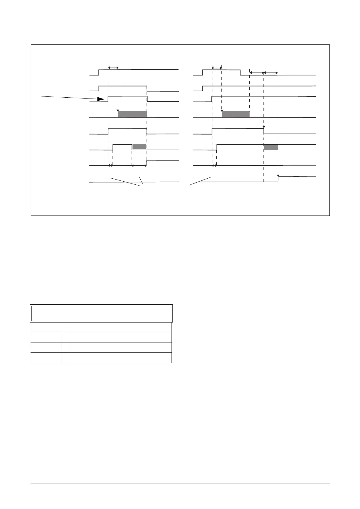
Fig. 108 Principle of Brake operation for fault during run and during stop.
Start Vector [33K]
Select the voltage vector applied at start. The start vector is
normally in the direction of the U-phase. It is also possible
to sequentially select different start vectors each start. This
can be advantageous as it distributes the wear more evenly
between different IGBTs. In particular if DC-start is used.
The start vector may also be selected based on the encoder
position (when applicable).
Brake warning
Brake Trip
Brake acknowledge
Brake relay
Speed>0
Torque
Running
Start
During run
During stop
Brake
<33H
33H
<33H
Brake
Brake wait
time
Brake engage
time
33F
33E
33C
33C
release time
release time
Brake Fault trip time
*
**
* Memorized load torque level, if function activated with parameter [33I] Release Torque.
** Time for operator to set down the load.
33K Start Vector
Default: 0
Normal (U) 0 U-phase
Sequence 1 Sequentially select different vectors
Encoder 2 Based on encoder position

 Loading...

