CG Drives & Automation 01-7491-01r0 153
Calculation:
AnIn1 = (8-0) / (10-0) x (1500-0) + 0 = 1200 rpm
AnIn2 = (4-0) / (10-0) x (1500-0) + 0 = 600 rpm
The actual process reference will be:
+1200 - 600 = 600 rpm
AnIn1 Setup [512]
The analogue input setup is used to configure the analogue
input in accordance with the signal used that will be
connected to the analogue input. With this selection the
input can be determined as current (4-20 mA) or voltage
(0-10 V) controlled input. Other selections are available for
using a threshold (live zero), a bipolar input function, or a
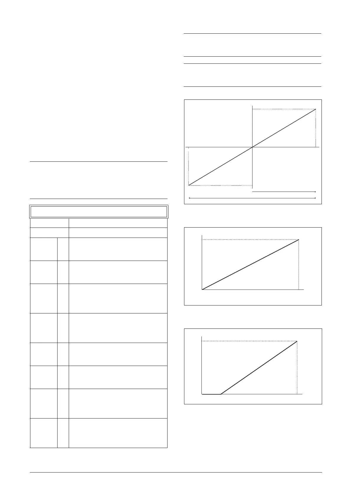
user defined input range. With a bipolar input reference
signal, it is possible to control the motor in two directions.
See fig. 130.
Fig. 130
Fig. 131 Normal full-scale configuration
Fig. 132 2–10 V/4–20 mA (Live Zero)
NOTE: The selection of voltage or current input is
done with S1. When the switch is in voltage mode
only the voltage menu items are selectable. With the
switch in current mode only the current menu items
are selectable.
512 AnIn1 Setup
Default: 4-20 mA
Dependent on Setting of switch S1
4–20mA 0
The current input has a fixed threshold
(Live Zero) of 4 mA and controls the full
range for the input signal. See Fig. 81.
0–20mA 1
Normal full current scale configuration of
the input that controls the full range for the
input signal. See Fig. 80.
User mA 2
The scale of the current controlled input,
that controls the full range for the input
signal. Can be defined by the advanced
AnIn Min and AnIn Max menus.
User Bipol
mA
3
Sets the input for a bipolar current input,
where the scale controls the range for the
input signal. Scale can be defined in
advanced menu AnIn Bipol.
0–10V 4
Normal full voltage scale configuration of
the input that controls the full range for the
input signal. See Fig. 80.
2–10V 5
The voltage input has a fixed threshold
(Live Zero) of 2 V and controls the full
range for the input signal. See Fig. 81.
User V 6
The scale of the voltage controlled input,
that controls the full range for the input
signal. Can be defined by the advanced
AnIn Min and AnIn Max menus.
User
Bipol V
7
Sets the input for a bipolar voltage input,
where the scale controls the range for the
input signal. Scale can be defined in
advanced menu AnIn Bipol.
NOTE: For bipol function, input RunR and RunL
needs to be active and Rotation, [219] must be set to
“R+L”.
NOTE: Always check the needed set up when the
setting of S1 is changed; selection will not adapt
automatically.
20 mA
100 %
100 %
n
(NG_06-F21)
10 V
0
-10 V
20mA
100 %
n
(NG_06-F21)
0
10 V

 Loading...

