CG Drives & Automation 01-7491-01r0 Installation 31
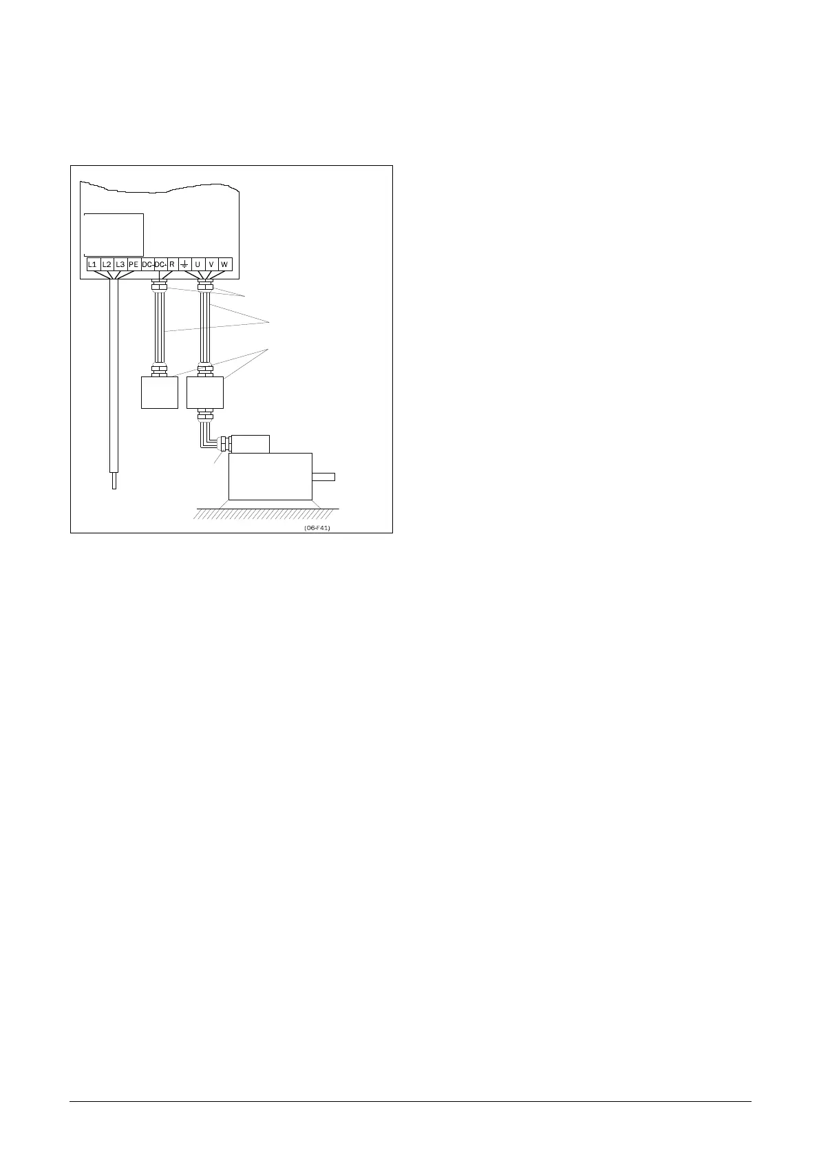
Fig. 43 shows an example when there is no metal mounting
plate used (e.g. if IP54 AC drives are used). It is important
to keep the “circuit” closed, by using metal housing and
cable glands.
Fig. 43 AC drive as stand alone.
Connect motor cables
1. Remove the cable interface plate from the AC drive
housing.
2. Put the cables through the glands.
3. Strip the cable according to table 15.
4. Connect the stripped cables to the respective motor
terminal.
5. Put the cable interface plate in place and secure
with the fixing screws.
6. Tighten the EMC gland with good electrical con-
tact to the motor and brake chopper cable screens.
Placing of motor cables
• Separate the power cables (AC drive, soft starter, output
coils, filters, magnetic switches, etc.) from the signal
cables (relay control circuit, PLC, sensors,
control PCBs, electronics, etc.).
• Keep the control cables as far from the power cables as
possible.
• If power cables and control cables must be laid close to
each other, try to ensure that they do not run parallel, at
least for a distance of no more than 300 mm (12 in).
If necessary, use a cable tray with a division or stack the
cable trays.
• Ensure that where power cables and control cables cross,
they do so at 90° to each other.
Long motor cables
If the connection to the motor is longer than 100 m
(330 ft)(for powers below 7.5 kW (10.2 hp)) please contact
CG Drives & Automation), it is possible that capacitive
current peaks will cause tripping at overcurrent. Using
output coils can prevent this. Contact the supplier for
appropriate coils.
Switching in motor cables
Switching in the motor connections is not advisable. In the
event that it cannot be avoided (e.g. emergency or
maintenance switches) only switch if the current is zero. If
this is not done, the AC drive can trip as a result of current
peaks.
Metal EMC cable
glands
Screened cables
Metal housing

 Loading...

