CG Drives & Automation 01-7491-01r0 Main Features 67
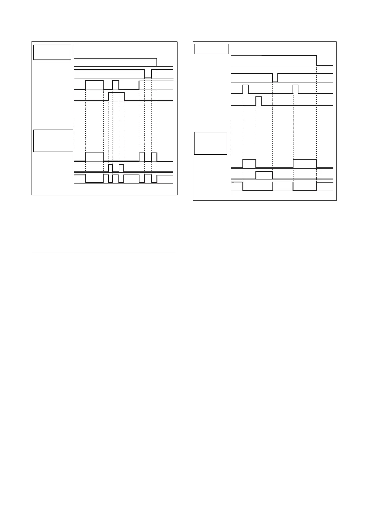
Fig. 73 Input and output status for level-control.
Run Inputs Edge-controlled
Menu “[21A] Start signal” Level/Edge must be set to Edge
to activate edge control. This means that an input is
activated by a “low” to “high” transition or vice versa.
See fig. 72. The Enable and Stop input must be active
continuously in order to accept any run-right or run-left
command. The last edge (RunR or RunL) is valid. fig. 74
gives an example of a possible sequence.
Fig. 74 Input and output status for edge-control.
NOTE: Edge-controlled inputs comply with the
Machine Directive (see chapter 8. page 79), if the
inputs are directly used for starting and stopping
the machine.
INPUTS
OUTPUT
STATUS
ENABLE
STOP
RUN R
RUN L
Right rotation
Left rotation
Standstill
INPUTS
ENABLE
STOP
RUN R
RUN L
OUTPUT
STATUS
Right rotation
Left rotation
Standstill

 Loading...

