CG Drives & Automation 01-7491-01r0 Main Features 73
Fig. 82 Feedback "Status" input.
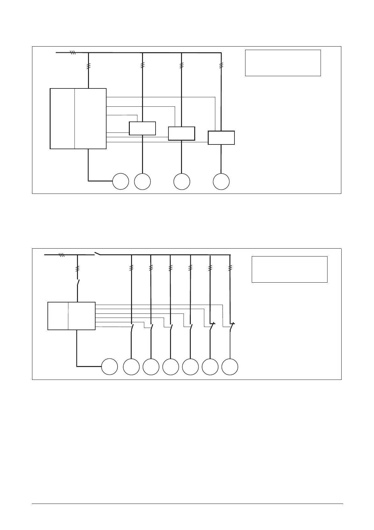
Fig. 83
Fail safe operationSome pump systems must always have a minimum flow or pressure level, even if the fre-
quency inverter is tripped or damaged. So at least 1 or 2 (or maybe all) additional pumps must keep running after the
inverter is powered down or tripped. This kind of "safe" pump operation can be obtained by using the NC contacts of
the pump control relays. These can be programmed for each individual additional pump. In this example, pumps P5
and P6 will run at maximum power if the inverter fails or is powered down.
Example of "Fail safe" operation.
P1 P2 P3
PM
FDU
MASTER
R:SlavePump3
R:SlavePump2
R:SlavePump1
DI:Pump1Feedb
DI:Pump2Feedb
DI:Pump3Feedb
other
drive
other
drive
other
drive
feedback
inputs
(NG_50-PC-6_1)
See menu:
[529] to [52H] Digital Input
[554] to [55C] Relay
P1 P2 P3 P4 P5 P6
PM
FDU
MASTER
R:SlavePump6
R:SlavePump5
R:SlavePump4
R:SlavePump3
R:SlavePump2
R:SlavePump1
(50-PC-7_1)
See menu:
[554] to [55C] Relays
[55D4] to [55DC] Mode

 Loading...

