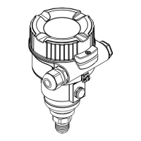
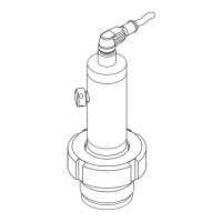
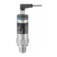
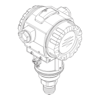
Cerabar M
20 Endress+Hauser
Connecting the valve connector M16, ISO4400
P01-PMx4xxxx-04-xx-xx-xx-009
BN = brown, BU = blue, GNYE = green/yellow
Supply voltage Note!
• When using the measuring device in hazardous areas, installation must comply with the corresponding
national standards and regulations and the Safety Instructions or Installation or Control Drawings.
• All explosion protection data are given in separate documentation which is available upon request. The
Ex documentation is supplied as standard with all devices approved for use in hazardous areas. → See also
Page 82, "Safety conventions and icons" and "Installation/Control Drawings" sections.
4 to 20 mA
For non-hazardous areas: 11.5 to 45 V DC
4 to 20 mA HART
For non-hazardous areas: 11.5 to 45 V DC
PROFIBUS PA
For non-hazardous areas: 9 to 32 V DC
Current consumption PROFIBUS PA: 11 mA ± 1 mA, switch-on current corresponds to IEC 61158-2, Clause 21
Cable entry → See also Page 67 ff, feature 20 "Housing; Electrical connection".
Cable specification • Endress+Hauser recommends using shielded, twisted pair two-wire cables.
• Terminals for wire cross-sections 0.14 to 2.5 mm
2
• Cable outer diameter: 5 to 9 mm
Residual ripple 4 to 20 mA and 4 to 20 mA HART
• Without impact on 4 to 20 mA signal up to ± 5% residual ripple within the permitted voltage range
(according to HART hardware specification HCF_SPEC-54 (DIN IEC 60381-1))
• With HART Communicator or Commubox:
Max. ripple (measured at 500 Ω) 47 to 125 Hz: U
ss
= 200 mV
Max. noise (measured at 500 Ω) 500 Hz to 10 kHz: U
eff
= 2.2 mV
123
12
+
-
BN BU GNYE
Cerabar M
4...20 mA
4...20 mA
1
2
3
4...20 mA
+
-

 Loading...


