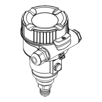
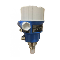
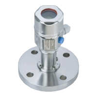
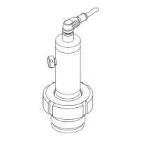
Cerabar M
Endress+Hauser 51
Process connections PMP48
(with metal measuring
diaphragm)
Note!
• The following tables contain information on the temperature coefficients "T
K
Process" and "T
K
Ambient". The
values given are typical values. These temperature coefficients apply to silicone oil and diaphragm material
AISI 316L/1.4435. For other filling oils, these temperature coefficients must be multiplied by the
T
K
correction factor of the corresponding filling oil. For the T
K
correction factors, see Page 60, "Diaphragm
seal filling oils" section.
• The following drawings are schematic diagrams. This means that the dimensions of a diaphragm seal
supplied can deviate from the dimensions indicated in this document.
• The tables and drawings always give the maximum installation height for the device version, i.e. this
installation height applies to a device with an aluminum housing and a raised cover and without any
capillaries. The installation heights for devices with a stainless steel housing and a raised cover are approx.
5 mm less.
• The tables always give the maximum total weight for the device version, i.e. this total weight applies to a
device with an aluminum housing and a raised cover. Devices with a stainless steel housing weigh approx.
300 g less.
Threaded connection, flush-mounted diaphragm
P01-PMP48xxx-06-09-xx-xx-000
Process connections PMP48, left: thread ISO 228, right: thread ANSI, material AISI 316L
h
h
x
1
G
d
1
d
2
d
M
x
1
d
M
NPT
d
2
SW
AF
SW
AF
h
h
x
1
G
d
1
d
2
d
M
x
1
d
M
NPT
d
2
SW
AF
SW
AF
H
H
Version Thread Nominal
pressure
Dia-
meter
Dia-
meter
Screw-in
length
Across
flats
Height Max.
diaphragm
diameter
T
K
Ambient
T
K
Process
Max. in-
stalla-
tion
height
Max.
total
weight
PN d
1
d
2
x
1
SW/AF h d
M
H
[mm] [mm] [mm] [mm] [mm] [mbar/10 K] [mm] [kg]
AF G 1 A 400 30 39 21 32 19 30 +16.03 +5.17 199 1.6
AG
1
G 1 1/2 A 400 43 55 30 41 20 42 +5.4 +1.76 200 2.1
AR G 2 400 56 68 30 60 20 50 +1.76 +0.56 200 3.1
BF 1 MNPT 400 – 48 28 41 37 24 +15.66 +4.21 217 1.8
BG 1 1/2 MNPT 400 – 50 30 41 20 36 +8.14 +2.59 200 2.1
BR 2 MNPT 400 – 78 30 65 35 38 +5.4 +2.59 235 3.0
1) Endress+Hauser also offers welding necks for this process connection. → See Page 34.

 Loading...


