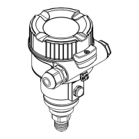
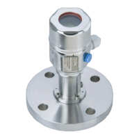
Cerabar M
54 Endress+Hauser
EN/DIN flanges, connection dimensions as per EN 1092-1/DIN 2527 and DIN 2501-1
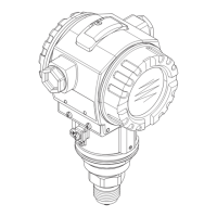
P01-PMP48xxx-06-09-xx-xx-001
Process connection PMP48, EN/DIN flange with flush-mounted diaphragm, material AISI 316L
H max. installation height = 235 mm + flange thickness b (→ see Table)
L
g
k
D
g
d
M
d
M
d
3
g
2
b
40
f
max. 235
H
Flanges Boltholes Diaphragm seal
Version Nomi-
nal dia-
meter
Nominal
pressure
Shape
1
Dia-
meter
Thick
ness
Raised face Qua
ntity
Dia-
meter
Hole
circle
Max.
diaphragm
diameter
T
K
Ambient
T
K
Process
Max.
total
weight
Dbgf g
2
kd
M
[mm] [mm] [mm] [mm] [mm] [mm] [mm] [mbar/10 K] [kg]
EB DN 25 PN 10-40 B1 (D) 115 18 66 3 4 14 85 32 +16.03 +5.17 2.1
EC DN 25 PN 63-160 E 140 24 68 2 4 18 100 28 +16.03 +5.17 2.5
ED DN 25 PN 250 E 150 28 68 2 4 22 105 28 +16.03 +5.17 3.7
EF DN 25 PN 400 E 180 38 68 2 4 26 130 28 +16.03 +5.17 7.0
EK DN 50 PN 10-40 B1 (D) 165 20 102 3 4 18 125 59 +2.21 +1.15 3.0
EM DN 50 PN 63 B2 (E) 180 26 102 3 4 22 135 59 +2.21 +1.15 4.6
EN DN 50 PN 100-
160
E 195 30 102 3 4 26 145 59 +2.21 +1.15 6.2
EP DN 50 PN 250 E 200 38 102 3 8 26 150 59 +2.21 +1.15 7.7
ER DN 50 PN 400 E 235 52 102 3 8 30 180 59 +2.21 +1.15 14.7
EU DN 80 PN 10-40 B1 (D) 200 24 138 3.5 8 18 160 89 +0.19 +0.11 5.3
FK
2
DN 50 PN 10-40 B1 (D) 165 20 102 3 4 18 125 47 +3.45 +1.67
2
GK
2
JK
2
FU
2
DN 80 PN 10-40 B1 (D) 200 24 138 3.5 4 18 160 72 +0.19 +0.7
2
GU
2
JU
2
1) Designation as per DIN 2527 in brackets
2) Alternatively with 50 mm, 100 mom and 200 mm extended diaphragm seal, for extended diaphragm seal diameter and weight, see the following table

 Loading...


