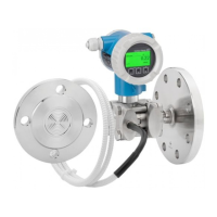
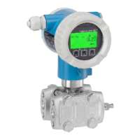
Deltabar FMD71, FMD72 Product description
Endress+Hauser 13
3.2 Function
3.2.1 Differential pressure generation
The measurement chain for the calculation of the differential pressure can be represented
by the following diagram:
Sensor
pressure LP
Measured
pressure LP
↑ ↑
LP →
Sensor
calibration LP
→
Sensor trim LP
→
Pressure
simulation LP
Corrected
pressure
Pressure after
damping
Measured
differential
pressure
↓
↑ ↑ ↑
Differential
pressure +
pressure
inversion
→
Position
adjustment
(calib. offset)
→
Differential
pressure
simulation
→ Damping → P
↑
HP →
Sensor
calibration HP
→
Sensor trim
HP
→
Pressure
simulation HP
↓ ↓
Sensor
pressure HP
Measured
pressure HP
All the process values represented on the diagram are updated in a measurement cycle.
The sensor module allocation is determined by the configuration when setting up the
device. The connection to the transmitter defines the corresponding sensor module as the
master. After commissioning, the second sensor module is detected as the slave. This
configuration can be modified as desired. However, a modification must take place with
the unit disconnected from the power supply.
The sensor modules have a designation independent of the master/slave configuration.
This indicates where the sensor module is typically installed:
• Sensor module LP
LP = Low pressure; top
• Sensor module HP
HP = High pressure; bottom
For identical sensor module ranges, this assignment can likewise be changed, but this then
has to be configured in the menu.
If you change both sensor modules or the electronics, this allocation must likewise be
carried out. See the "Transm. connect. (286)" parameter .

 Loading...